Automatic driving system applied to road sweeping vehicle and control method and device thereof

An automatic driving and road cleaning technology, which is applied in the direction of non-electric variable control, two-dimensional position/channel control, vehicle position/route/height control, etc., can solve the problem of increasing road congestion, slow driving speed, and road cleaning vehicle size Large and other problems, to achieve the effect of low cost, saving labor costs, and reducing traffic pressure during the day

Active Publication Date: 2018-09-04
CHERY AUTOMOBILE CO LTD
View PDF12 Cites 44 Cited by
  • Summary
  • Abstract
  • Description
  • Claims
  • Application Information

AI Technical Summary

Benefits of technology

This technology allows for automatic detection and monitoring around vehicles through various sensors such as LIDAR (Laser Imaging Detection System), cameras or laser scanners that help with better environmental awareness on roads while maintaining efficient operation. It also saves time and money compared to manual methods like brushes up after hours. Overall, this technology helps improve efficiency and productivity across different types of transportation systems.

Problems solved by technology

This patented technical problem addressed in this patents relates to improving the performance of street sweeps while reducing their impact upon drivers working intensively overnight hours or when they don’t have enough time to actively use them themselves.

Method used


Image

  • Automatic driving system applied to road sweeping vehicle and control method and device thereof
  • Automatic driving system applied to road sweeping vehicle and control method and device thereof
  • Automatic driving system applied to road sweeping vehicle and control method and device thereof

Examples


Embodiment Construction

[0052] In order to make the object, technical solution and advantages of the present invention clearer, the implementation manner of the present invention will be further described in detail below in conjunction with the accompanying drawings.

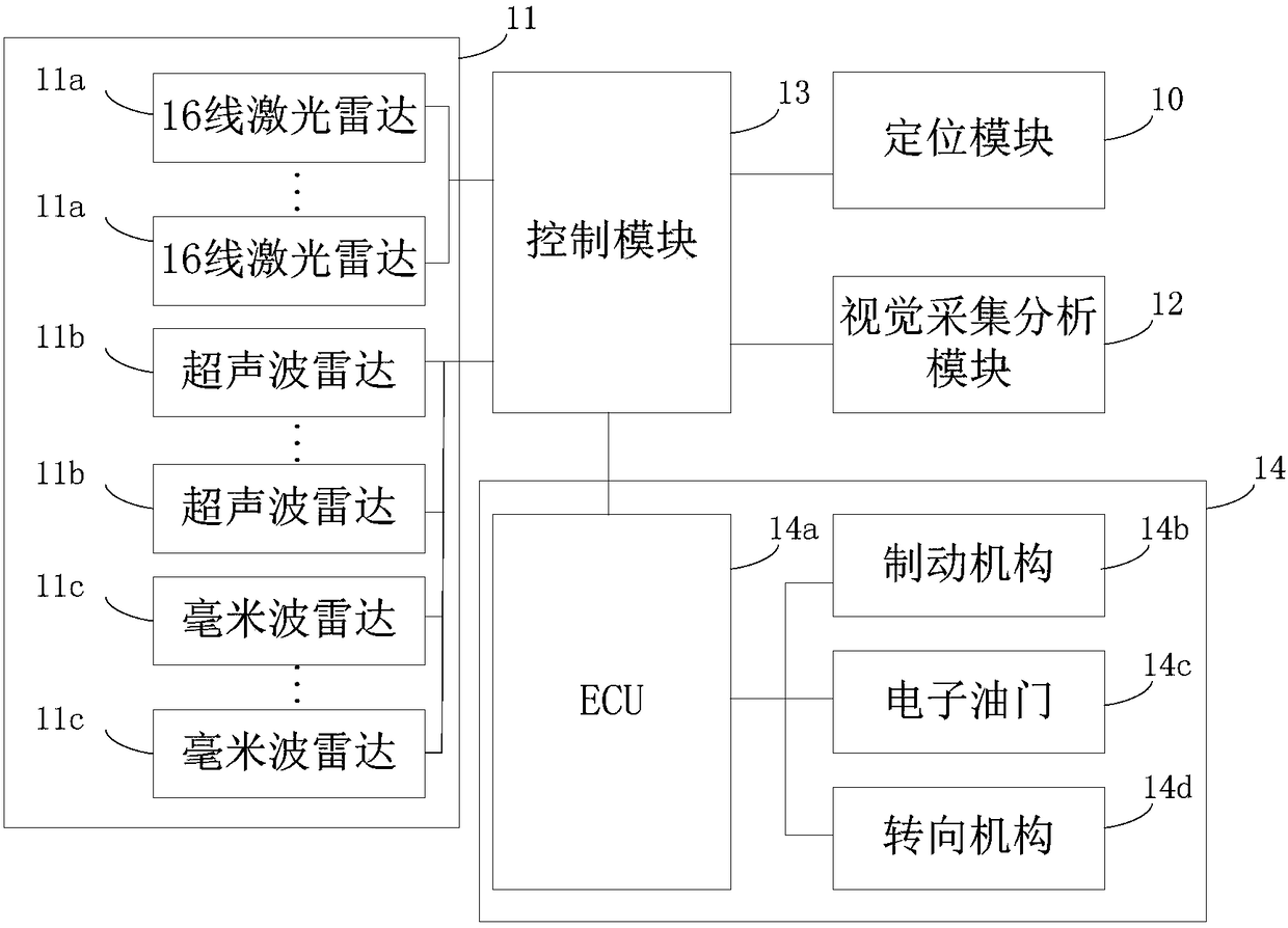
[0053] figure 1 It shows an automatic driving system applied to a road sweeper provided by an embodiment of the present invention. see figure 1 , the system includes a positioning module 10 , several radars 11 , a visual collection and analysis module 12 , a control module 13 and a bottom-level execution module 14 .

[0054] Wherein, the positioning module 10 is used for detecting the real-time position of the vehicle.

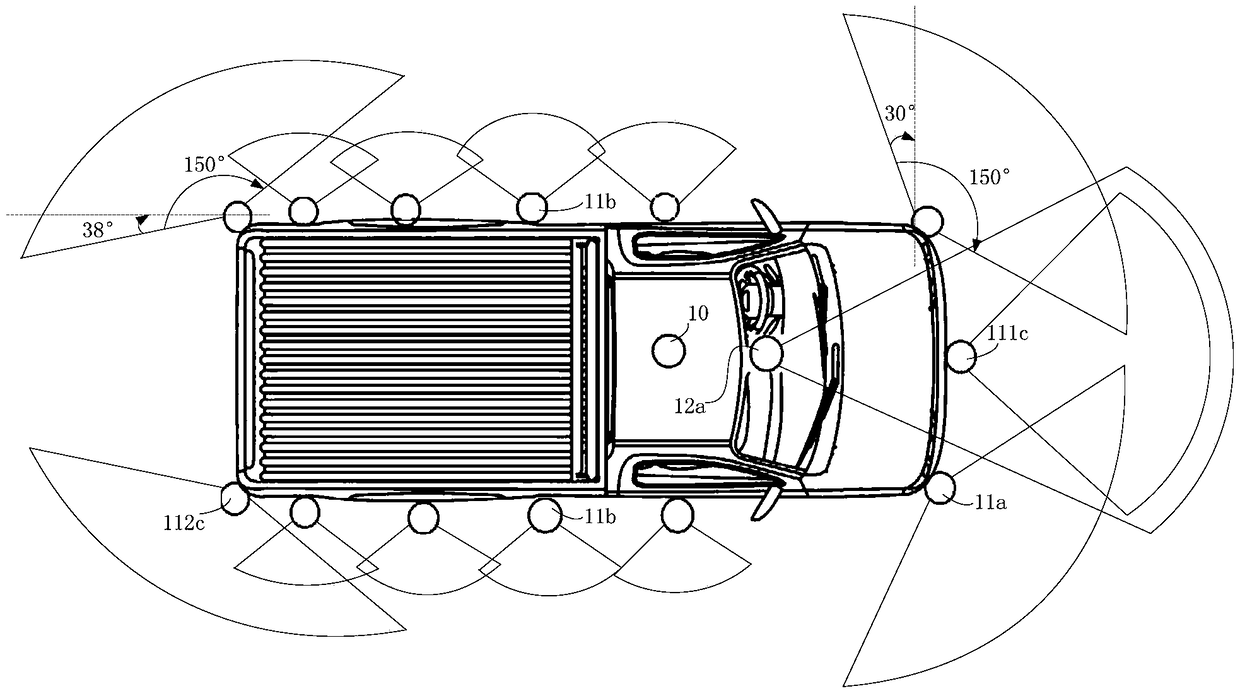
[0055] Among them, the several radars 11 may include several 16-line laser radars 11a, several ultrasonic radars 11b, and several millimeter wave radars 11c. For example, the several radars 11 include at least two 16-line laser radars 11a, at least eight ultrasonic radars 11b, and at least three millimeter wave rada...


PUM


Abstract

The invention discloses an automatic driving system applied to a road sweeping vehicle and a control method and device thereof, which belongs to the technical field of automatic driving. The system comprises a positioning module, a number of radars, a visual acquisition and analysis module, a control module and an underlying execution module. A lidar detects obstacles in front of the driving vehicle and on both sides of the front of the driving vehicle and detects road edges on both sides of the front of the driving vehicle. An ultrasonic radar detects obstacles on both sides of the vehicle. Amillimeter wave radar detects the type of obstacles in front of the driving vehicle, behind the driving vehicle and on both sides behind the driving vehicle, calculates the distance and relative speed between a dynamic obstacle and the vehicle. The visual acquisition and analysis module detects a travelable area in front of the driving vehicle, a road stop line in front of the driving vehicle, obstacles and traffic lights in front of the driving vehicle, and the distance between the front wheels of the vehicle and lane lines on both sides of a driving lane. The control module determines the driving road and driving policy of the vehicle based on detection information. The vehicle is controlled to drive on the driving road according to the driving policy.

Description


Claims


Application Information

Patent Timeline
Owner CHERY AUTOMOBILE CO LTD
Why Eureka
Try Eureka