
Short-shaft rotary self-balancing mechanism

A rotary, self-balancing technology, applied to agricultural machinery, agricultural machinery and implements, applications, etc., can solve problems such as deviation of implements, difference between operating depth of tillage and set depth of tillage, and incomplete crushing of operations, etc., to achieve changing adjustment methods Effect

Pending Publication Date: 2018-09-07
NANJING AGRI MECHANIZATION INST MIN OF AGRI +1
View PDF8 Cites 0 Cited by
  • Summary
  • Abstract
  • Description
  • Claims
  • Application Information

AI Technical Summary

Problems solved by technology

[0003] However, most of the working places of agricultural machinery are on uneven ground, which leads to obvious deviations in the operation process of the equipment. There will be a big difference in the fixed tillage depth; the straw crushing equipment will also cause incomplete crushing in the operation due to the unevenness of the ground, which will lead to poor rotary tillage effect
There are also some manufacturers in China who consider these factors and invent some implements, but the results are not ideal. For example, some manufacturers add balance adjustment devices to the supporting plates of the implements during design, and some manufacturers add some auxiliary mechanisms between the implements and the tractor. The mechanism is basically a passive adjustment method, and cannot be actively adjusted.

Method used


Image

  • Short-shaft rotary self-balancing mechanism
  • Short-shaft rotary self-balancing mechanism
  • Short-shaft rotary self-balancing mechanism

Examples


Embodiment 1

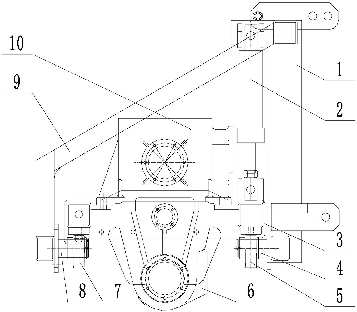
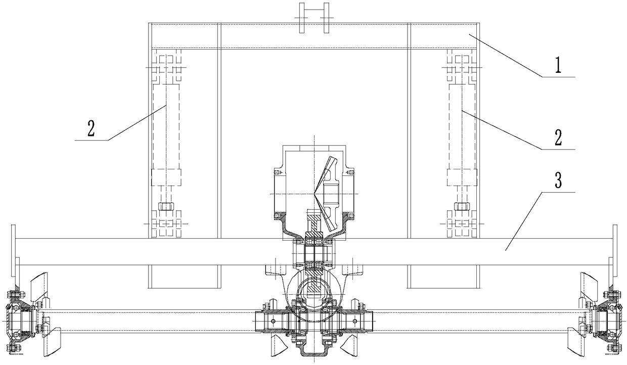
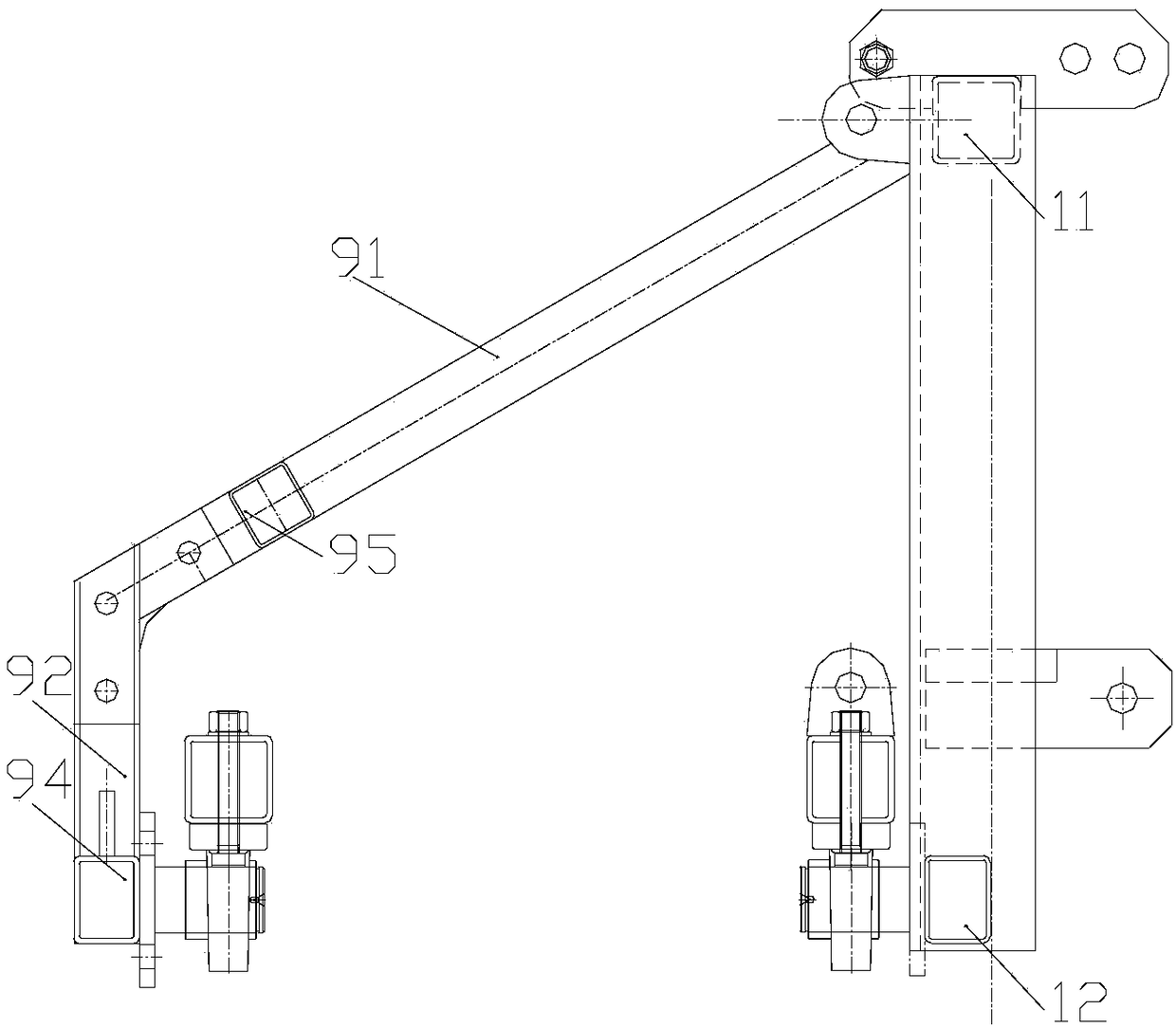
[0019] Embodiment 1: as figure 1 The short-axis rotary self-balancing mechanism shown includes a frame, and the frame includes a detachable suspension 1, a suspension beam 9 and a frame 3, the detachable suspension 1 and the frame 3 are square frames, and the detachable suspension 1 is Set vertically, the top of the suspension beam 9 is connected to the top of the separate suspension 1 to form a balance adjustment bracket, and the frame 3 is horizontally arranged between the bottom of the separate suspension 1 and the bottom of the suspension beam 9; the bottom of the separate suspension 1 is installed with a rear protruding The front beam rotation short shaft 4, the bottom of the suspension beam 9 is equipped with a forward protruding back beam rotation short shaft 8, the front beam and the rear beam of the frame 3 are connected to the front beam rotation short shaft through the front beam short shaft coupling 5 and the rear beam short shaft coupling 7 respectively. Axis 4 an...


PUM


Abstract

The invention discloses a short-shaft rotary self-balancing mechanism. The mechanism comprises a split suspension, a suspension beam and a frame. The top of the suspension beam is connected with the top of the split suspension to form a balance adjustment bracket, and the frame is horizontally disposed at the bottom of the split suspension and the bottom of the suspension beam. The bottom of the split suspension is provided with a front beam rotating short shaft, the bottom of the suspension beam is provided with a rear beam rotating short shaft, and a front beam and a rear beam of the frame are respectively rotatably connected with the front beam rotating short shaft and the rear beam rotating short shaft through front beam short shaft coupling and rear beam short shaft coupling; an adjustment oil cylinder is arranged between the split suspension and the frame, the frame is provided with a sensor and a controller, the sensor is used for collecting tilt angles of the frame and transmitting to the controller, the controller is connected with the adjustment oil cylinder through a solenoid valve, the controller outputs a driving signal to the solenoid valve to control the movement ofthe adjustment oil cylinder, and the adjustment oil cylinder acts to drive the frame to rotate around the the front beam rotating short shaft and the rear beam rotating short shaft to a balance state.The mechanism can achieve active adjustment of machines and tools.

Description

technical field [0001] The invention relates to the technical field of agricultural machinery, in particular to a short axis rotating self-balancing mechanism. Background technique [0002] At present, most of the tillage machinery is powered by tractors. The connection methods of implements and tractors can be divided into direct traction type and three-point suspension type, and the three-point suspension connection method is more widely used, such as land preparation machinery Among the rotary tillage machines, plows, subsoilers, and straw crushing and returning machines, the three-point suspension farm tools are widely used due to the structure of the tractor. [0003] However, most of the working places of agricultural machinery are on uneven ground, which leads to obvious deviations in the operation process of the equipment. There will be a big difference in the fixed tillage depth; straw crushing equipment will also cause incomplete crushing in the operation due to t...

Claims


Application Information

Patent Timeline
Patent Type & Authority Applications(China)
IPC IPC(8): A01B59/06
CPCA01B59/067
Inventor 陈伟陈小兵朱继平袁栋姚克恒丁艳夏敏孙传东
Owner NANJING AGRI MECHANIZATION INST MIN OF AGRI
Learn More