
Riveting die

A mold and riveting technology, applied in the field of riveting equipment, can solve problems such as low riveting efficiency and achieve the effect of improving production efficiency

Inactive Publication Date: 2018-09-07
ZHENJIANG GANGLONG MECHANICAL & ELECTRICAL
View PDF0 Cites 0 Cited by
  • Summary
  • Abstract
  • Description
  • Claims
  • Application Information

AI Technical Summary

Problems solved by technology

[0003] The invention provides a riveting die, which solves the problem of low efficiency of traditional riveting

Method used


Image

  • Riveting die

Examples


Embodiment Construction

[0013] The present invention will be further described below in conjunction with the accompanying drawings. The following examples are only used to illustrate the technical solution of the present invention more clearly, but not to limit the protection scope of the present invention.

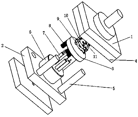
[0014] Such as figure 1 As shown, the riveting mold includes an upper mold 1, a lower mold 2 and a slider 3.

[0015] A punch 4 is arranged on the bottom surface of the upper die 1, and the punch 4 is a rectangular plate, and the bottom surface of the punch 4 has several guide holes.

[0016] The top surface of the lower die 2 is provided with a boss 6 and a number of guide posts 5, the guide posts 5 match the guide holes, the boss 6 is a cylindrical boss, and N riveting heads 7 are vertically arranged on the top of the boss 6. The head 7 is consistent with the number of rivets 11 to be riveted.

[0017] There are N through holes on the slider 3, and the N through holes are respectively match...


PUM


Abstract

The invention discloses a riveting die. The riveting die comprises an upper die, a lower die and a sliding block. A punch is arranged on the bottom face of the upper die, a boss is arranged on the topface of the lower die, N riveting heads are vertically arranged on the top face of the boss, N through holes are formed in the sliding block, the N through holes are matched with the N riveting heads, the sliding block penetrates through the N riveting heads, and a containing groove matched with an ignition lock base is formed in the top face of the sliding block. Riveting of all rivets on the ignition lock base can be completed at a time, and the production efficiency is improved.

Description

technical field [0001] The invention relates to a riveting die, which belongs to the field of riveting equipment. Background technique [0002] Several copper rivets are riveted on the base of the ignition lock, and these rivets function as contacts. The traditional riveting method is to use a rivet gun to rivet individually on the bottom plate, which is inefficient. Contents of the invention [0003] The invention provides a riveting die, which solves the problem of low efficiency of traditional riveting. [0004] In order to solve the problems of the technologies described above, the technical solution adopted in the present invention is: [0005] The riveting mold includes an upper mold, a lower mold and a slider. A punch is arranged on the bottom surface of the upper mold, a boss is arranged on the top surface of the lower mold, N riveting heads are vertically arranged on the top surface of the boss, and there are holes on the slider. N through holes, the N through h...

Claims


Application Information

Patent Timeline
Patent Type & Authority Applications(China)
IPC IPC(8): B21D37/10B21D39/00
CPCB21D37/10B21D39/00
Inventor 闵鹏茂梁少伟
Owner ZHENJIANG GANGLONG MECHANICAL & ELECTRICAL
Learn More