
A unilateral positioning cam drive mechanism for continuous zoom lens

A technology of unilateral positioning and driving mechanism, which is applied in the directions of instruments, installation, optics, etc., and can solve problems such as low image plane consistency, application limitations, curved grooves and positioning pins stuck, etc.

Active Publication Date: 2021-03-26
西安应用光学研究所
View PDF9 Cites 0 Cited by
  • Summary
  • Abstract
  • Description
  • Claims
  • Application Information

AI Technical Summary

Problems solved by technology

[0004] For the motor direct drive mode, the optical sliding assembly can achieve precise positioning under the drive of the motor, and then realize the precise continuous zoom function; this mechanism is widely used in continuous zoom lenses with fewer optical sliding components. The continuous zoom lens with an optical slide assembly is limited in application due to the need for more motors and position sensors, and the complexity of the mechanism and control circuit
[0005] For the cam drive method, the curve sleeve in a cam mechanism can process multiple sets of drive curves, so it can simultaneously drive multiple sets of optical sliding components to achieve continuous zooming, and has been widely used; however, due to the difficulty of processing the cam curve and the Due to the limitation of processing accuracy, especially for the processing stress of the curved groove, the consistency of the drive positioning groove walls on both sides of the curved groove is reduced, resulting in the system's continuous zooming process. The consistency of the image plane is not high, and the movement of the driving optical slider is not stable. At the same time, due to the high and low temperature load (temperature range from -45°C to 60°C), the curved groove and positioning pin in the driving mechanism are often stuck.

Method used


Image

  • A unilateral positioning cam drive mechanism for continuous zoom lens
  • A unilateral positioning cam drive mechanism for continuous zoom lens
  • A unilateral positioning cam drive mechanism for continuous zoom lens

Examples


Embodiment Construction

[0032] Embodiments of the present invention are described in detail below, and the embodiments are exemplary and intended to explain the present invention, but should not be construed as limiting the present invention.

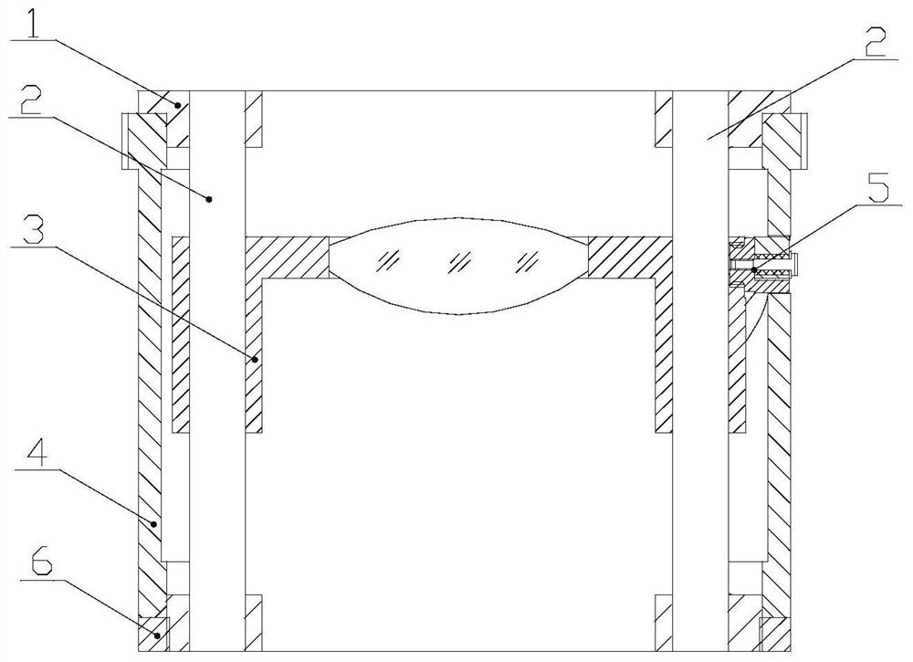
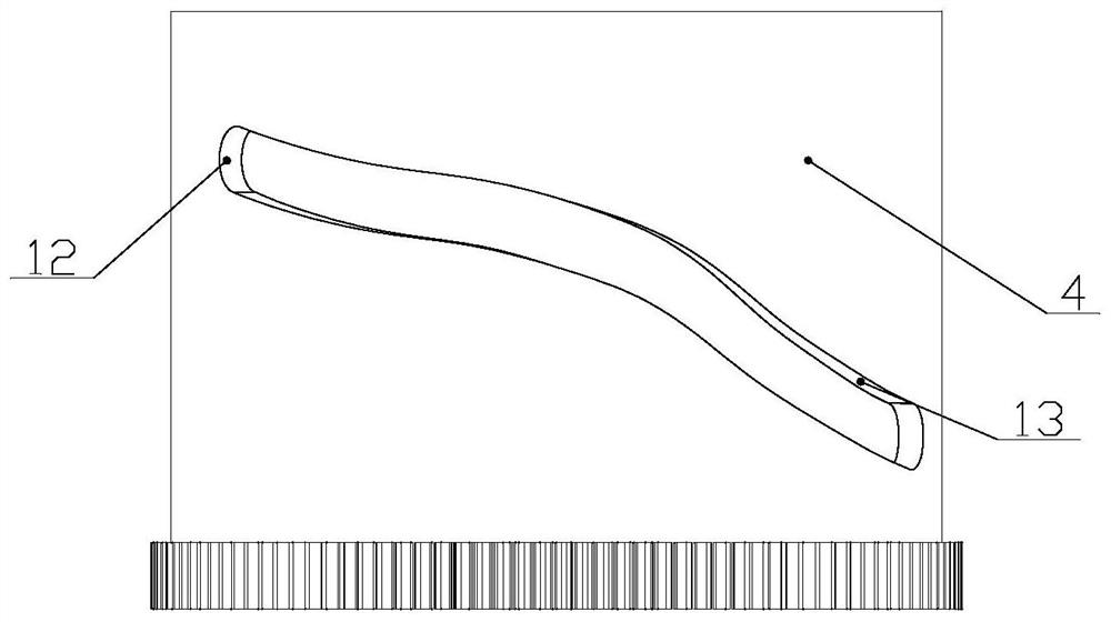
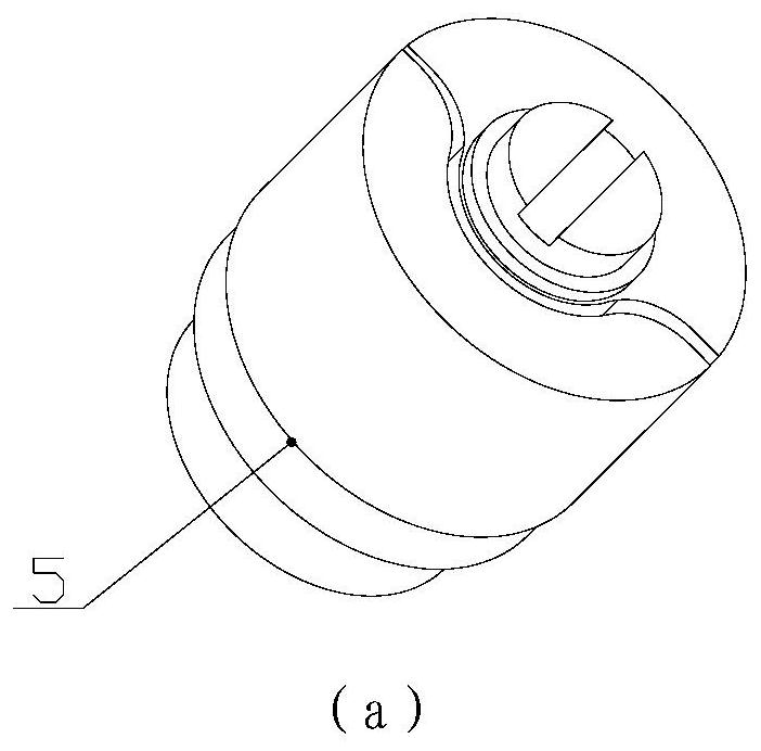
[0033] like figure 1 , a sectional view of a single-side positioning cam drive mechanism for a continuous zoom lens, including a main bracket 1, a sliding rod 2, an optical sliding assembly 3, a single-side positioning curve sleeve 4, a semi-flexible pin assembly 5, a locking pressure ring 6, Unilateral positioning pin 7, elastic column sleeve 8, pressing pin 9, pressing sheet 10, fixing nail 11.

[0034] Wherein, the optical sliding assembly 3 is connected with the main bracket 1 through the sliding rod 2, and the sliding rod 2 is fixed with the main bracket 1. Under the constraint of the sliding rod 2, the optical sliding assembly 3 does not rotate relative to the main bracket 1 along the sliding rod 2. linear sliding; the unilateral positioning curve sleev...


PUM


Abstract

The invention discloses a single-side positioning cam driving mechanism for a continuous zoom lens. Includes main bracket, slide rod, optical slide assembly, single-sided positioning curve sleeve, semi-flexible pin assembly, and locking retainer. The optical sliding assembly is connected to the main bracket through a sliding rod, and the sliding rod is fixed on the main bracket. The optical sliding assembly makes a non-rotating linear motion along the sliding rod relative to the main bracket; the unilateral positioning curve sleeve is coaxially connected with the main bracket through a locking ring The unilateral positioning curve sleeve can rotate along the central axis relative to the main bracket; the semi-flexible pin component passes through the curved groove of the unilateral positioning curve sleeve in the radial direction and is fixed with the optical sliding component. By rotating the unilaterally positioned curved sleeve around the central axis, the optical sliding assembly is driven to move linearly along the slide bar, thereby realizing the axial movement of the optical element in the continuous zoom lens. The invention uses a semi-flexible pin assembly and a single-side positioning curve sleeve to reduce the difficulty of system processing and assembly, and improve the accuracy of the system and the temperature applicability of the system.

Description

technical field [0001] The invention relates to a continuous zoom driving mechanism, in particular to a single-side positioning cam driving mechanism for a continuous zoom lens, which belongs to the category of precision optical-mechanical design. Background technique [0002] The continuous zoom optomechanical system has been widely used due to its characteristics such as continuous change of focal length, large zoom ratio, coaxial multi-field of view, and compact structure. The continuous zoom system changes the focal length of the entire system by moving multiple lens groups in the system. On the premise of keeping the position of the image plane unchanged, it can achieve continuous and clear images during the entire zooming process. [0003] At present, there are mainly two driving modes of continuous zooming: motor direct drive and motor driven cam mechanism drive. [0004] For the motor direct drive mode, the optical sliding assembly can achieve precise positioning un...

Claims


Application Information

Patent Timeline
Patent Type & Authority Patents(China)
IPC IPC(8): G02B7/04G02B7/08G02B7/10
CPCG02B7/04G02B7/08G02B7/10
Inventor 王谭腾国奇吴英春高健健赵玮施道云袁屹杰惠进张卫国
Owner 西安应用光学研究所
Learn More