Synchronizer gear engagement process control method based on unilateral pressure control system

A technology of pressure control and process control, which is applied in the direction of transmission control, components with teeth, belts/chains/gears, etc. It can solve the problems of inability to deal with the decline of control performance, and achieve the effect of reducing repeated gearing failures

Active Publication Date: 2018-09-07
JILIN UNIV
View PDF9 Cites 17 Cited by
  • Summary
  • Abstract
  • Description
  • Claims
  • Application Information

AI Technical Summary

Problems solved by technology

[0003] According to the working principle of the synchronizer, the staged control method is mostly used to control it, but this control method cannot deal with the problem of the decline in control performance caused by the wear of the synchronizer components, and cannot efficiently handle the failure of the gear to ensure that Accuracy and timeliness of re-engaging action

Method used


Image

  • Synchronizer gear engagement process control method based on unilateral pressure control system
  • Synchronizer gear engagement process control method based on unilateral pressure control system
  • Synchronizer gear engagement process control method based on unilateral pressure control system

Examples


Embodiment Construction

[0061] The present invention will be further described in detail below in conjunction with the accompanying drawings, so that those skilled in the art can implement it with reference to the description.

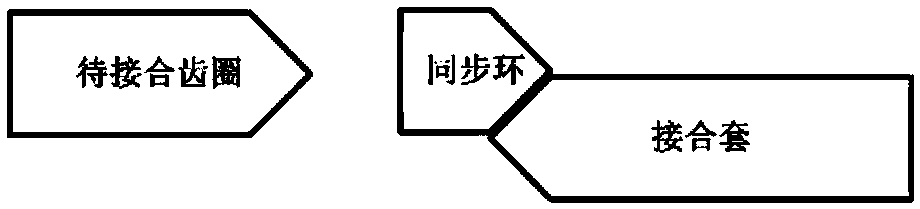
[0062] like Figure 1-7 As shown, the analysis of the locking ring synchronizer gearing process can be divided into 7 special position points and 6 stages:

[0063] Stage1: The first free travel of the coupling sleeve, from point A to point B in the figure, that is, from the steady-state neutral position point to the synchronization start point;

[0064] The synchronous shift fork drives the adapter sleeve to move axially from point A of the neutral position until the end surface of the adapter sleeve contacts the end surface of the synchronization ring. This stage can be subdivided into two processes according to the change of resistance:

[0065] The adapter sleeve moves axially from point A of the neutral position until the end surface of the slide block contacts with th...


PUM


Abstract

The invention discloses a synchronizer gear engagement process control method based on a unilateral pressure control system. On the premise of meeting the power requirement of a driver, according to the conditions of high requirement for matching precision of the synchronizer pressure control logic, differentiation of controlling different boxes through the same matching parameter and the complexity of the actual working conditions, the failure frequency of gear engagement of a synchronizer can be reduced, the working efficiency of the synchronizer is improved, gear engagement impact is small,no obvious noise is generated, the service life of the synchronizer is prolonged, and the method has good engineering practicality.

Description

technical field [0001] The invention relates to a synchronizer control method, in particular to a synchronizer gear-in process control method based on a unilateral pressure control system. Background technique [0002] The lock ring synchronizer controls it in stages according to the mechanical structure and working principle. The specific automatic control methods include: synchronizer pre-filling stage, pre-synchronization stage, synchronization stage, secondary meshing stage, pressure relief stage and completely in the gear stage; synchronizer detaching stage, synchronizer combined with idle stroke stage, synchronizer sliding and grinding combined stage, synchronizer combined with idle stroke stage, synchronizer pressing stage and synchronizer in gear stage; eliminate idle stroke stage, the first Secondary synchronization stage, free stroke stage and second synchronization to the end stage of synchronizer gear; first free stroke stage; overcoming positioning pin resistanc...

Claims


Application Information

Patent Timeline
Patent Type & Authority Applications(China)
IPC IPC(8): F16H61/04F16H61/12F16H61/28
CPCF16H61/0403F16H61/12F16H61/2807F16H2306/48
Inventor 雷雨龙张煜晨付尧程靖刘科张琳悦王林波
Owner JILIN UNIV
Why Eureka
Try Eureka