
An Adaptive Closed-loop Measurement System of Resonant Accelerometer

A technology of accelerometer and measurement system, which is applied in speed/acceleration/shock measurement, acceleration measurement using inertial force, and acceleration measurement. Contradictions between bandwidth and response speed, reducing system reliability and other issues, to achieve the effect of improving stability, simple structure, and improving linearity

Active Publication Date: 2020-09-18
BEIJING INST OF AEROSPACE CONTROL DEVICES
View PDF9 Cites 2 Cited by
  • Summary
  • Abstract
  • Description
  • Claims
  • Application Information

AI Technical Summary

Problems solved by technology

The frequency control of existing resonant accelerometers mostly adopts the form of phase-locked loop, and the loop filter is mostly based on PI control. However, due to the fixed PI parameters, the contradiction between bandwidth and response speed cannot be solved, which limits the range of the accelerometer. , bias stability, scale factor linearity and other indicators
[0003] Some literatures propose methods such as fuzzy PID control and neural network PID control to adjust PI parameters online, but the algorithm is too complicated, which will reduce the reliability of the system and greatly occupy hardware resources.
At the same time, the signal amplitude demodulation module of the existing resonant accelerometer mostly adopts rectification filtering, peak detection and other methods, which will occupy more hardware resources

Method used


Image

  • An Adaptive Closed-loop Measurement System of Resonant Accelerometer
  • An Adaptive Closed-loop Measurement System of Resonant Accelerometer
  • An Adaptive Closed-loop Measurement System of Resonant Accelerometer

Examples


Embodiment Construction

[0035] In order to better understand the present invention, the content of the present invention will be further described in detail below in conjunction with the accompanying drawings and specific embodiments.

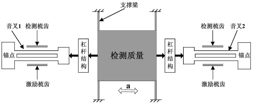
[0036] Such as figure 1 As shown, each silicon microresonant accelerometer includes a detection mass located in the middle, a lever structure is arranged symmetrically on both sides of the detection mass, and a tuning fork is connected to the outside of the lever structure, as well as detection combs and excitation combs. When the detection mass generates axial inertial force under the action of external axial acceleration, the force is amplified by the lever structure and transmitted to the tuning fork. The tuning fork is respectively fixed at two symmetrical anchor points of the MEMS structure and vibrates at a natural frequency. Under the action of inertial force, the natural frequency of the vibration of the tuning fork changes. The axial inertial force produces ...


PUM


Abstract

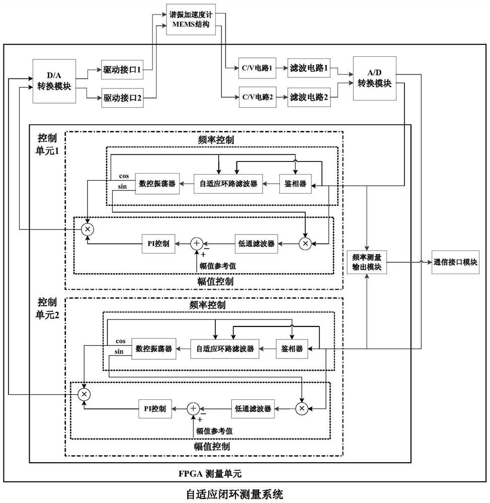
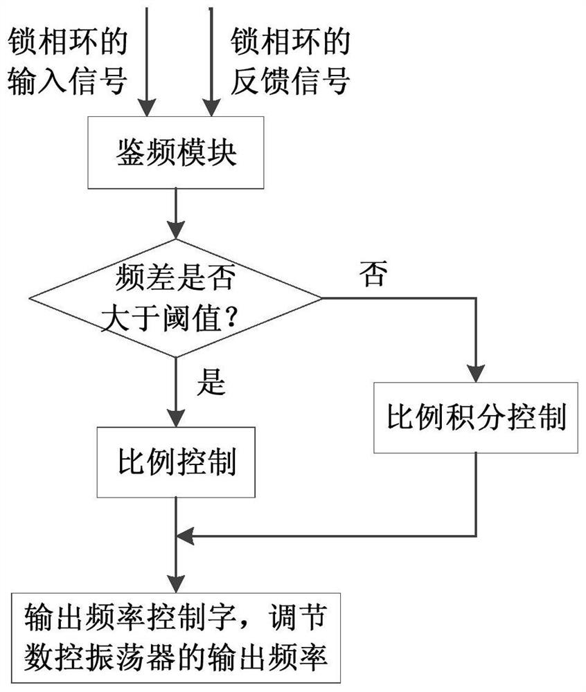
The invention discloses a self-adaptive closed-loop measuring system of a resonant accelerometer, the frequency control adopts a self-adaptive control phase-locked loop structure, and the control modeof a loop filter can be automatically selected according to the change of the external acceleration, the problems that in the prior art, circuit parameters are fixed, and self-adaptive adjustment cannot be achieved are solved, and the contradiction between the response speed and the steady-state phase difference of the phase-locked loop is effectively overcome, so that the measuring range, the scale factor linearity and the zero bias stability of the accelerometer are effectively improved. Meanwhile, the structure is simple, a complex algorithm is not needed, and the system has the advantagesof being simple, efficient and high in adaptability. A PI control unit adopts an incremental algorithm, the improvement of a traditional position type PI algorithm is achieved, a better control effect can be obtained, and the stability of the system is improved; an amplitude control module adopts an alternating current automatic gain control method, a simple and effective amplitude demodulation method is adopted in the module, hardware resources are saved, and the amplitude of the driving signals can be adjusted within a large range.

Description

technical field [0001] The invention belongs to the technical field of MEMS accelerometers, and relates to a signal detection and drive control system design method of the accelerometer, in particular to a closed-loop measurement technology of the MEMS silicon microresonance accelerometer. Background technique [0002] Silicon microresonant accelerometers have the advantages of small size, low power consumption, quasi-digital output, and great potential for accuracy improvement. They have good application prospects and have become a research hotspot in the field of inertial research at home and abroad in recent years. The frequency control of existing resonant accelerometers mostly adopts the form of phase-locked loop, and the loop filter is mostly based on PI control. However, due to the fixed PI parameters, the contradiction between bandwidth and response speed cannot be solved, which limits the range of the accelerometer. , bias stability, scale factor linearity and other...

Claims


Application Information

Patent Timeline
Patent Type & Authority Patents(China)
IPC IPC(8): G01P15/097
CPCG01P15/08G01P15/097G01P2015/0862
Inventor 杨博徐宇新邢朝洋胡启方
Owner BEIJING INST OF AEROSPACE CONTROL DEVICES
Learn More