A bonding method, system, device and device

A coordinate system and camera technology, applied in the field of bonding methods, equipment and devices, and systems, can solve the problems of high error rate, a large amount of manpower, and low efficiency of manual bonding products, and achieve the effect of high accuracy

Active Publication Date: 2020-10-16
GUANGZHOU SHIYUAN ELECTRONICS CO LTD +1
View PDF5 Cites 0 Cited by
  • Summary
  • Abstract
  • Description
  • Claims
  • Application Information

AI Technical Summary

Problems solved by technology

However, the commonly used bonding method still adopts manual operation. The efficiency of manually bonding products is relatively low. In addition, a large amount of manpower is required to repeat the bonding operation, and the error rate is relatively high. Once a mistake is made, it is easy to cause resource failure. waste of

Method used


Image

  • A bonding method, system, device and device
  • A bonding method, system, device and device
  • A bonding method, system, device and device

Examples


Embodiment 1

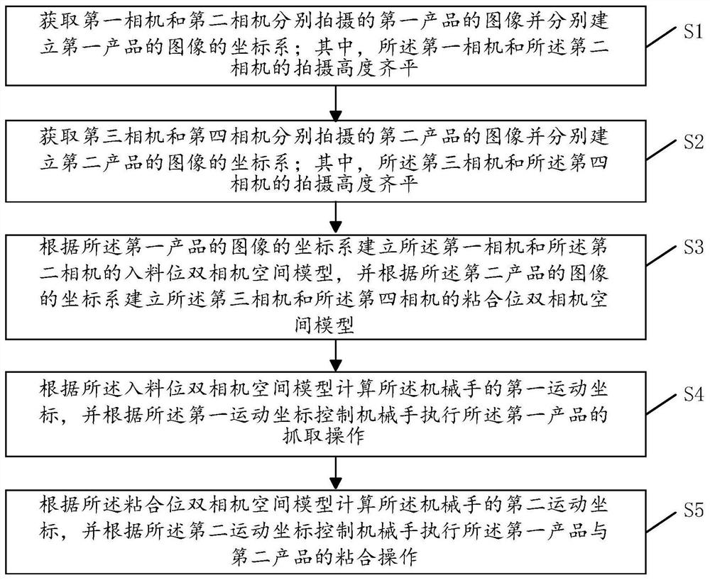
[0061] see figure 1 , figure 1 It is a flowchart of a bonding method provided in Embodiment 1 of the present invention; including:

[0062] S1. Obtain the images of the first product captured by the first camera and the second camera respectively, and respectively establish the coordinate system of the images of the first product; wherein, the shooting heights of the first camera and the second camera are at the same level;

[0063] S2. Obtain the images of the second product respectively captured by the third camera and the fourth camera and respectively establish the coordinate system of the images of the second product; wherein, the shooting heights of the third camera and the fourth camera are at the same level;

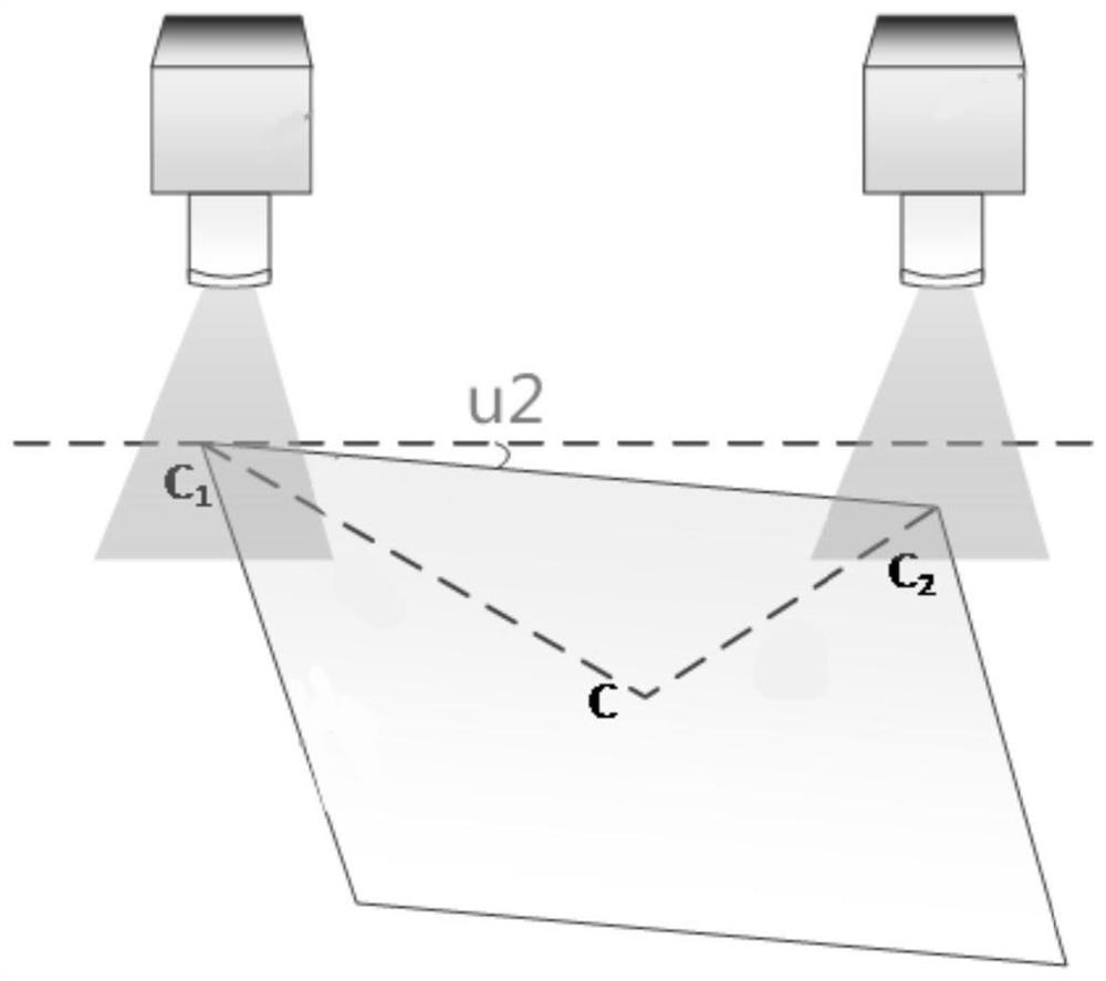
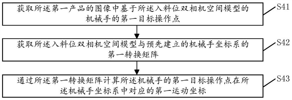
[0064] S3. Establish a dual-camera space model of the first camera and the second camera at the feed level according to the coordinate system of the image of the first product, and establish the first camera according to the coordinate system of the image of the...

Embodiment 2

[0106] see Figure 9 , Figure 9 It is a structural schematic diagram of an adhesive system 20 provided in Embodiment 2 of the present invention; including:

[0107] The product image acquiring unit 21 is used to acquire the images of the first product taken by the first camera and the second camera respectively and respectively establish the coordinate system of the images of the first product, and is also used to acquire the images taken by the third camera and the fourth camera respectively. The image of the second product and establish the coordinate system of the image of the second product respectively; Wherein, the shooting height of the first camera and the second camera are equal, and the shooting height of the third camera and the fourth camera flush;

[0108] The dual-camera space model unit 22 is used to establish the dual-camera space model of the first camera and the second camera according to the coordinate system of the image of the first product; The coordi...

Embodiment 3

[0141] see Figure 12 , Figure 12 It is a schematic structural diagram of a bonding device 30 provided in Embodiment 3 of the present invention; the bonding device 30 of this embodiment includes: a processor 31, a memory 32, and A computer program that runs. When the processor 31 executes the computer program, the steps in the above-mentioned embodiments of the bonding method are realized, for example figure 1 Steps S1-S5 are shown. Or, when the processor 31 executes the computer program, it realizes the functions of each unit in the above embodiment of the bonding system, for example, the function of the product image acquisition unit 21 .

[0142] Exemplarily, the computer program can be divided into one or more modules / units, and the one or more modules / units are stored in the memory and executed by the processor 31 to implement the present invention . The one or more modules / units may be a series of computer program instruction segments capable of accomplishing speci...


PUM


Abstract

The invention discloses a bonding method which comprises the following steps: acquiring images of a first product shot by a first camera and a second camera respectively; acquiring images of a secondproduct shot by a third camera and a fourth camera; establishing a feeding position double-camera space model of the first camera and the second camera, and establishing a bonding position double-camera space model of the third camera and the fourth camera; calculating the first motion coordinate of a mechanical arm according to the feeding position double-camera space model, and controlling the mechanical arm to execute the grabbing operation of the first product according to the first motion coordinate; calculating a second motion coordinate of the mechanical arm according to the bonding position double-camera space model, and controlling the mechanical arm to execute the bonding operation of the first product and the second product according to the second motion coordinate. The invention further discloses a bonding system, a bonding device and a bonding apparatus. According to the invention, automatic bonding of products can be realized, and the precision is high.

Description

technical field [0001] The invention relates to the field of product bonding in the manufacturing industry, in particular to a bonding method, system, equipment and device. Background technique [0002] The bonding of planar products is a key stage in the manufacture of multi-layer products. When making multi-layer products, planar products need to be pasted in sequence, and the bonding operation needs to be strictly controlled during the pasting process, so as to ensure the flatness of each layer. Products are aligned one by one, such as the bonding of double-adhesive paper, the edges of each layer of double-adhesive paper correspond to each other during the bonding operation. For high-end products, the bonding standards are even higher. However, the commonly used bonding method still adopts manual operation. The efficiency of manually bonding products is relatively low. In addition, a large amount of manpower is required to repeat the bonding operation, and the error rate...

Claims


Application Information

Patent Timeline
Patent Type & Authority Patents(China)
IPC IPC(8): G06T7/70G06T7/13G06T7/80B25J9/04B25J9/16F16B11/00
CPCB25J9/041B25J9/1679F16B11/006G06T7/13G06T7/70G06T7/80G06T2207/20061G06T2207/20164
Inventor 戴嵘
Owner GUANGZHOU SHIYUAN ELECTRONICS CO LTD
Why Eureka
Try Eureka