Plastic separation device

A separation device and plastic technology, applied in the direction of plastic recycling, recycling technology, etc., can solve the problem of difficult to take out half inlays

Inactive Publication Date: 2018-09-14
宁波隆锐机械制造有限公司
View PDF1 Cites 0 Cited by
  • Summary
  • Abstract
  • Description
  • Claims
  • Application Information

AI Technical Summary

Problems solved by technology

[0004] The purpose of the present invention is to provide a plastic separating device to

Method used


Image

  • Plastic separation device
  • Plastic separation device
  • Plastic separation device

Examples


Example Embodiment

[0017] The present invention will be further described in detail below through specific implementations:

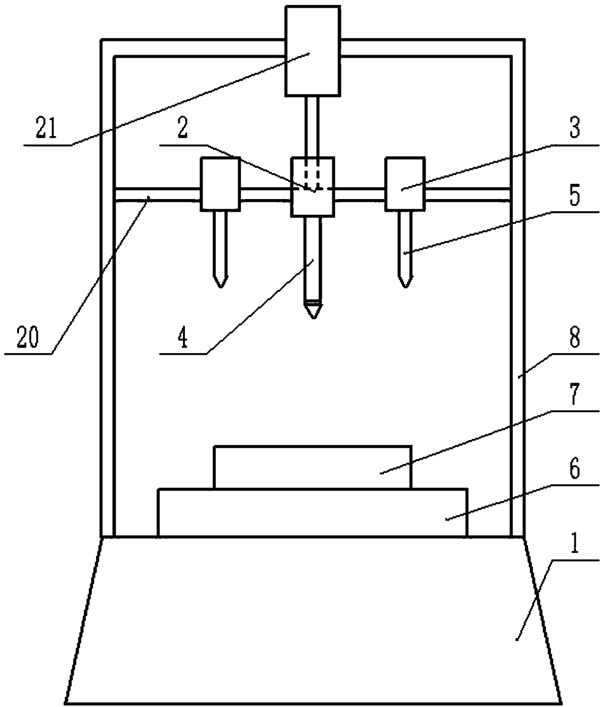
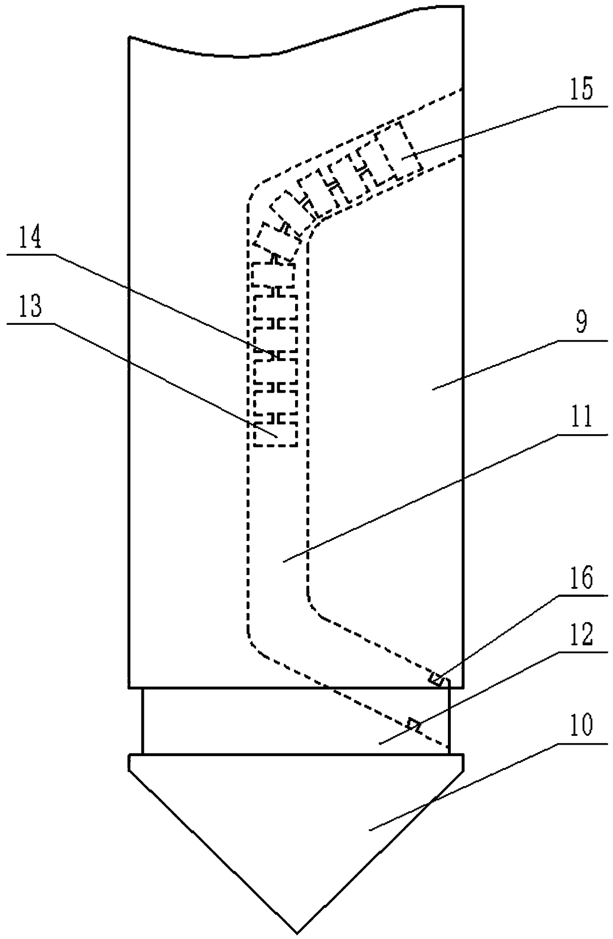
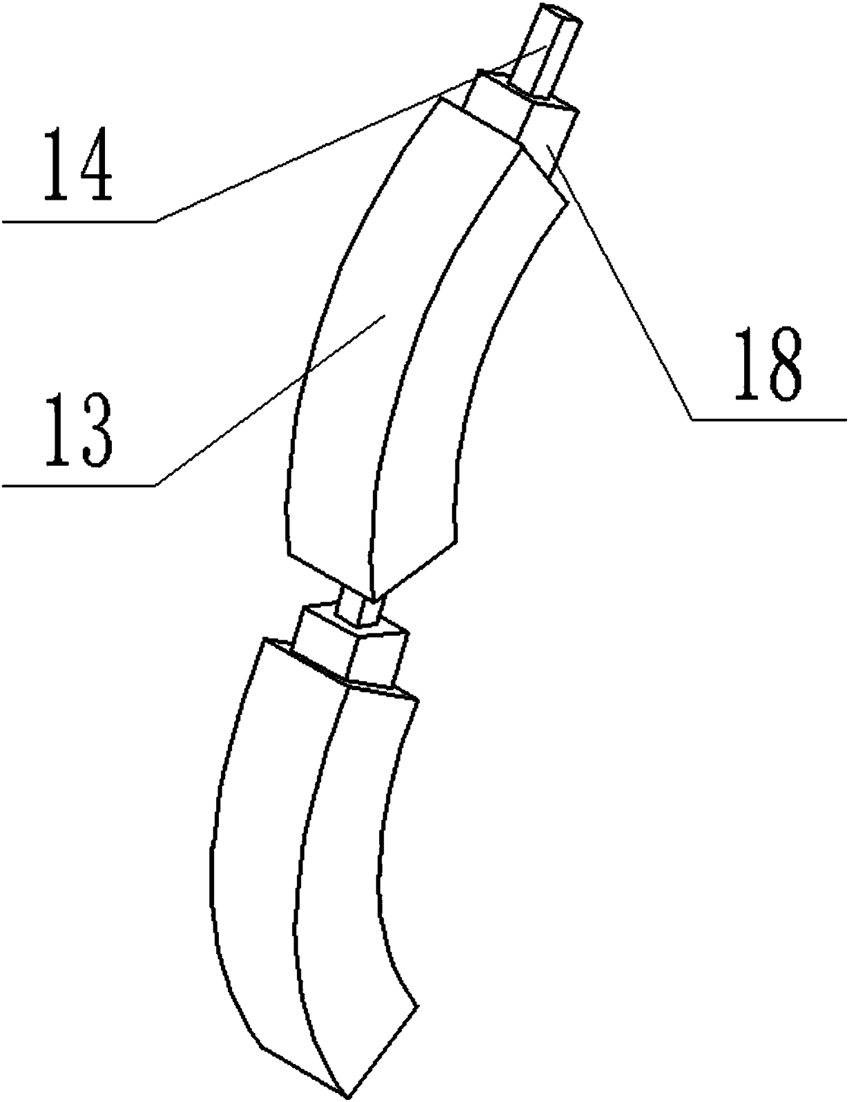
[0018] The reference signs in the drawings of the specification include: processing table 1, main motor 2, auxiliary motor 3, main cutter 4, auxiliary cutter 5, clamping seat 6, elastic clamping block 7, bracket 8, cutter body 9, cutter head 10. The cavity 11, the knife groove 12, the blade 13, the connecting strip 14, the sliding block 15, the limiting plate 16, the limiting block 17, the protrusion 18, the groove 19, the horizontal frame 20, and the air cylinder 21.

[0019] Such as figure 1 , figure 2 As shown, the plastic separation device of this embodiment includes a processing table 1, a clamping base 6, a support 8, a main motor 2 and a sub-motor 3. The clamping base 6 is welded to the center of the upper end surface of the processing table 1, and an annular elastic clamping block 7 is fixed on the clamping base 6. The bracket 8 is welded to the upper end surface of ...


PUM


Abstract

The invention belongs to the technical field of separation devices, and particularly discloses a plastic separation device which comprises a processing platform, a clamping device for clamping a plastic product and a support. A transverse frame is arranged on the support, a main motor and an auxiliary motor are arranged on the transverse frame, pin holes are formed in the main motor and the auxiliary motor, the transverse frame is provided with inserting holes aligned at the pin holes, and an inserting pin is arranged in each inserting hole; a main cutter is arranged on the main motor, an auxiliary cutter is arranged on the auxiliary motor, the main cutter comprises a cutter body and a cutter bit integrally formed at the bottom of the cutter body, a cavity is formed inside the cutter body,the upper end of the cavity extends to the upper portion of the outer wall of the cutter body while the lower end of the same extends to the lower portion of the same, the cutter body is circumferentially provided with an annular cutter groove, a chain cutter is slidably arranged in the cavity and comprises a plurality of blades in sequential connection and a connection strip movably connected with the blades, and height of the blades is smaller than that of the cutter groove while width of the same is smaller than that of the cavity. The invention aims to solve the problem that annular half-embedded objects in plastic products are difficult to be taken out.

Description

technical field [0001] The invention belongs to the technical field of separation devices, and specifically discloses a plastic separation device. Background technique [0002] Many plastic products are equipped with inlays, some are used for decoration, and some inlays have functional functions, such as shaft sleeves, etc. These plastic products can be recycled after being discarded, but the inlays on them need to be recycled. take out. In the prior art, electric welding is mostly used to melt the connection between the plastic product and the inlay, and then the inlay is taken out. This method is inefficient, and toxic and harmful gases are likely to be generated when the plastic product is melted. [0003] Chinese patent announcement number CN103448162B discloses a plastic separator, which includes a separator main body and a press-down device, the press-down device is connected to the separator main body, and an operating table is provided on the upper end of the separa...

Claims


Application Information

Patent Timeline
IPC IPC(8): B29B17/02
CPCB29B17/02B29B2017/0217Y02W30/62
Inventor 李新平
Owner 宁波隆锐机械制造有限公司
Why Eureka
Try Eureka