
High-power rectifier device and DC pole-changing system

A rectifier, high-power technology, applied in the direction of converting irreversible AC power input to DC power output, etc., can solve the problems of arcing, overheating of contact elements, short life, etc., and achieve extended service life, reliable operation, and heat loss. reduced effect

Pending Publication Date: 2018-09-14
大连重工机电设备成套有限公司 +1
View PDF7 Cites 0 Cited by
  • Summary
  • Abstract
  • Description
  • Claims
  • Application Information

AI Technical Summary

Problems solved by technology

[0004] Aiming at the defects existing in the prior art, the technical problem to be solved by the present invention is to provide a high-power rectification device and a DC pole changing system, and a DC smelting furnace using the system. The rectification device adopts a vacuum contactor in the The rectifier diode branch is switched, which effectively avoids many problems such as overheating of contact elements, arcing, insulation damage, and short life in traditional methods

Method used


Image

  • High-power rectifier device and DC pole-changing system
  • High-power rectifier device and DC pole-changing system

Examples


Embodiment Construction

[0021] The specific embodiments of the present invention will be further described below in conjunction with the accompanying drawings.

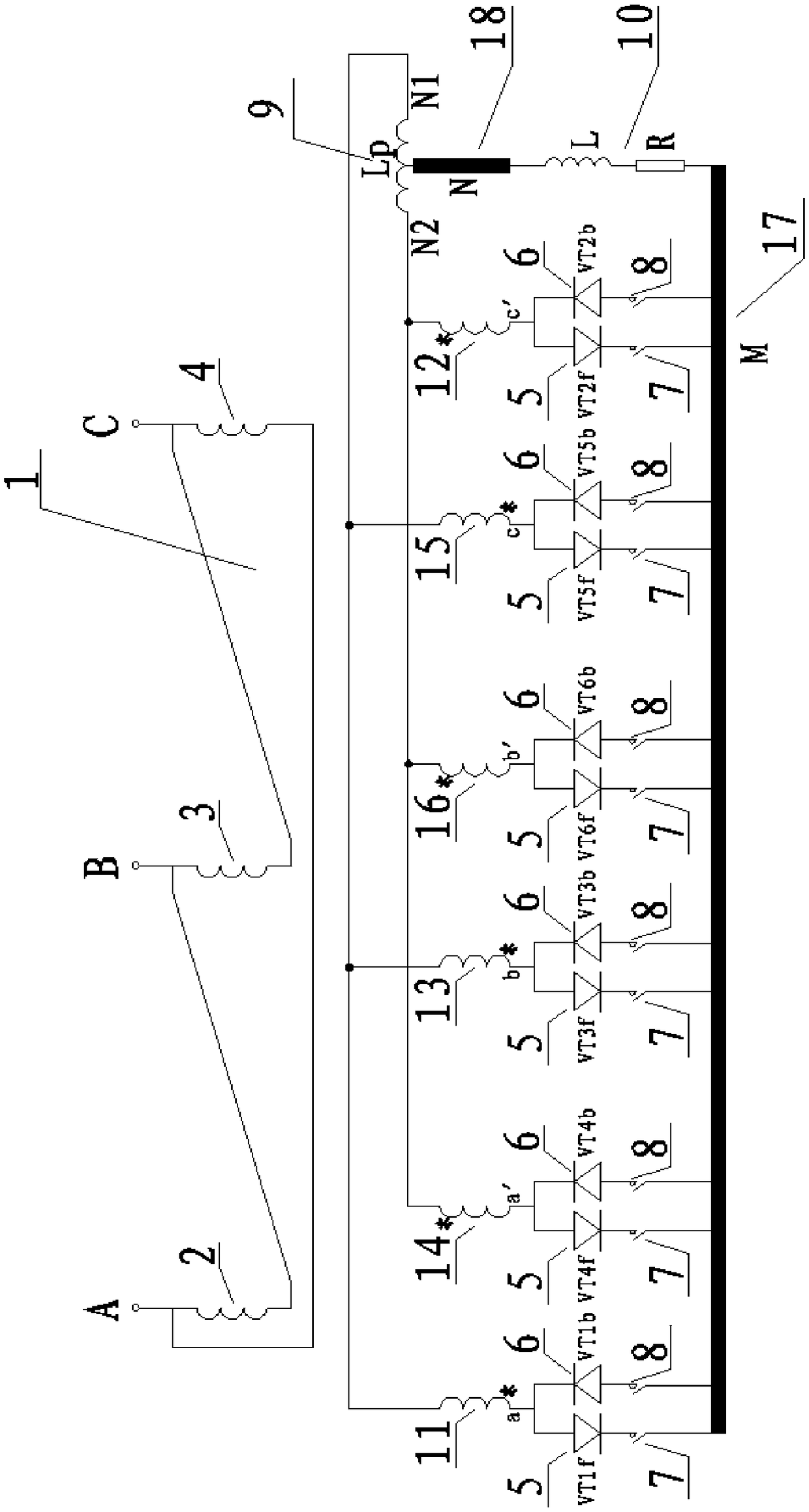
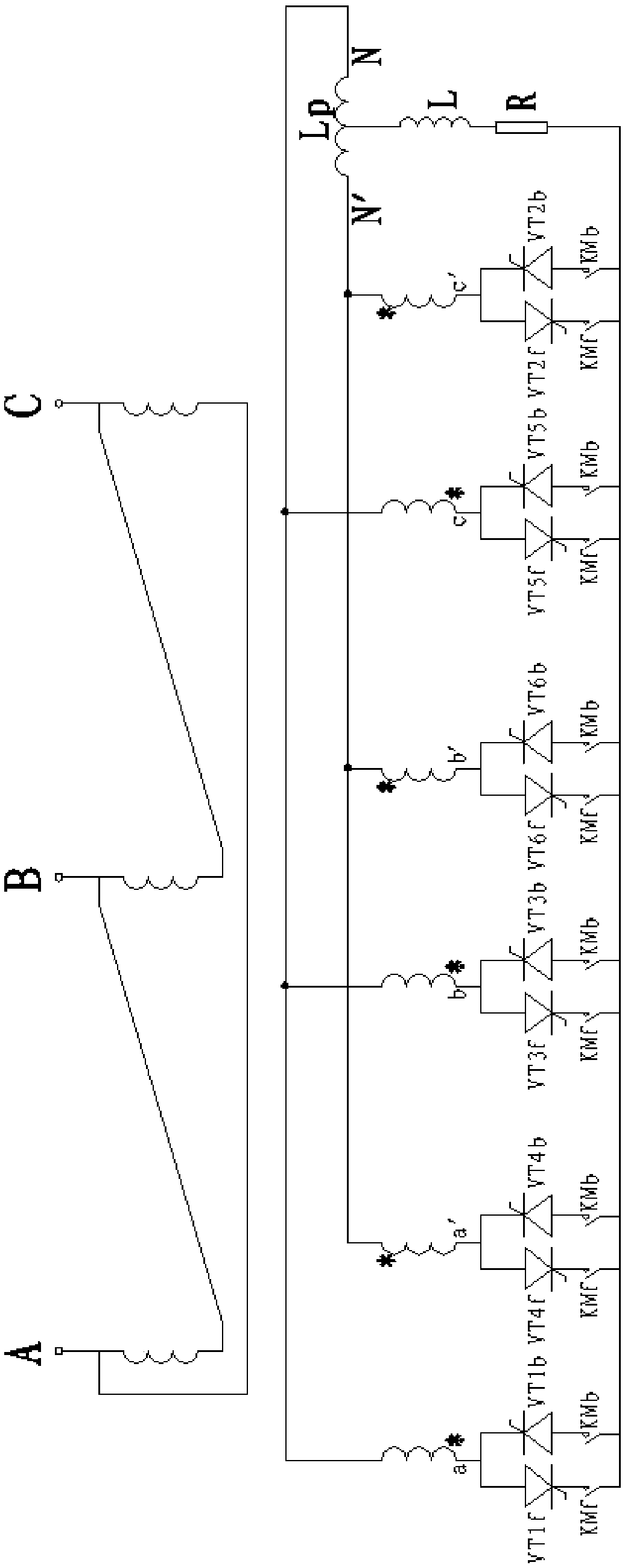
[0022] as attached figure 1 As shown in the rectification circuit section in , a high-power rectification device includes rectification diodes and switching switches. The rectification diodes are divided into two groups, one group is a forward diode group, and the other group is a reverse diode group. Each Each rectifier diode is connected in series with a switching switch, and the switching on and off of the rectifying diode branch is controlled by the switching on and off of the switching switch. Further, the switching switches in which the diodes in each group of forward and reverse diode groups are connected in series one by one form a group of simultaneously controlled vacuum contactor groups. Further, the two groups of vacuum contactors corresponding to the forward and reverse diode groups The contactor groups are interlocked through ...


PUM


Abstract

The invention discloses a high-power rectifier device and a DC pole-changing system. The rectifying device comprises rectifying diodes and switching switches. The rectifying diodes are divided into two groups, one group is a forward diode group, and the other group is a reverse diode group, each of the rectifying diodes is connected to a switching switch in series, and the switch-on and switch-offof a switching diode branch are controlled by the switch-on and switch-off of the switching switch. The DC pole changing system is formed by a standard double-reversed star rectifying circuit with abalanced reactor and the above rectifier device. By adopting the DC pole-changing system of the invention, the DC polarity of high-power equipment can be frequently switched, by using a vacuum contactor in the rectifier device, the operation of DC polarity switching is more reliable and safe, the heat loss of a contact element is greatly reduced, and the service life of a switching element is greatly extended. Moreover, the on-load switching of positive and negative electrodes is further realized, and more means are provided for the on-load power-off protection in production.

Description

technical field [0001] The invention relates to the technical field of high-power electric energy transmission, in particular to an improvement of a high-power rectifying device and a DC pole changing system. Background technique [0002] At present, in industrial production, DC knife switches are often used to switch polarity on the DC output side of the rectifier device. However, due to the limitations of the knife switch itself, there may be overheating of contact elements, arcing, insulation damage, Short lifespan and many other issues. [0003] The prior art "Configuration Structure of DC Bus Pole Change" (application number: 201020658765.1) discloses a DC bus pole change configuration structure. A DC knife switch is installed on the upper end of the rectifier transformer device to switch the output positive and negative poles. It is switching on the DC side of the rectifier. The prior art "Conversion Device for Positive and Negative Electrodes of Rectifiers" (Applica...

Claims


Application Information

Patent Timeline
Patent Type & Authority Applications(China)
IPC IPC(8): H02M7/40H02M7/10
CPCH02M7/10H02M7/40
Inventor 谷端玉孙大庆王晓斌张学武张宏程赵霞
Owner 大连重工机电设备成套有限公司
Learn More