
A system and method for energy scheduling and management between cabinets in a data room

A technology of energy dispatching and data computer room, which is applied in information technology support system, power network operating system integration, emergency power supply arrangement, etc. It can solve the problems that the battery capacity of networked cabinets cannot be uniformly deployed, and the backup time cannot be configured separately.

Active Publication Date: 2020-07-24
XIANGJIANG TECH
View PDF8 Cites 0 Cited by
  • Summary
  • Abstract
  • Description
  • Claims
  • Application Information

AI Technical Summary

Problems solved by technology

[0014] Purpose of the invention: In order to overcome the deficiencies of the prior art, the present invention provides an energy scheduling management system and method among cabinets in a data room, which solves the problem that the battery capacity of the networking cabinets cannot be uniformly allocated, and the backup time of each cabinet cannot be configured separately to meet The problem of different backup time requirements of users

Method used


Image

  • A system and method for energy scheduling and management between cabinets in a data room
  • A system and method for energy scheduling and management between cabinets in a data room
  • A system and method for energy scheduling and management between cabinets in a data room

Examples


Embodiment 1

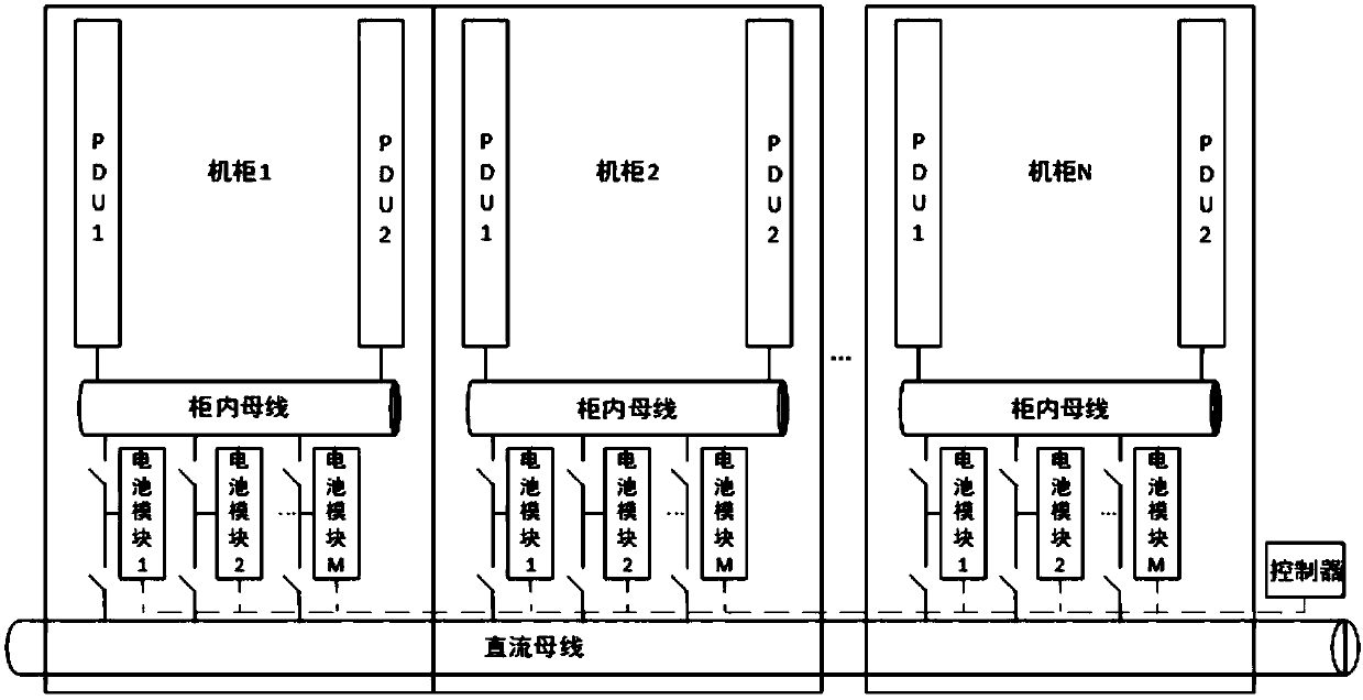
[0045] Such as figure 1 As shown, there are at least two cabinets, a DC bus connecting multiple cabinets, at least two battery modules in each cabinet, a bus in each cabinet and two PDUs, and the total number of cabinets is N.

[0046] Each PDU is connected to the busbar in the cabinet, and multiple loads are connected to the PDU. The two PDUs are respectively recorded as the first PDU and the second PDU. The first and second PDUs are connected to the busbar in the cabinet. The first PDU and the second PDU are connected to at least one electrical component, and the first PDU and the second PDU correspond to PDU1 and PDU2 in the figure.

[0047] The first PDU and the second PDU are used to receive the electric energy of the connected bus in the cabinet, and transmit the received electric energy to the connected electric components, and a plurality of battery modules and the The bus bars in the cabinet are connected through a plurality of first load switches, and the number of ...

Embodiment 2

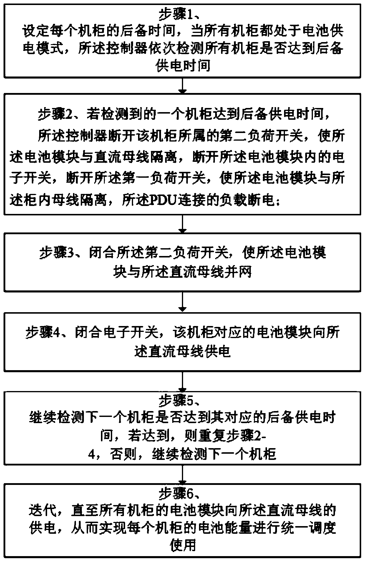
[0059] In addition, according to the system described in Embodiment 1, the present invention provides an energy scheduling management method between cabinets in a data room, such as image 3 As shown, the method realizes the monitoring of the power module and the load switch through the controller, and utilizes the cooperative action of the two load switches and the electronic switch in the battery module to jointly realize the on-load switching without using a circuit breaker, including:

[0060] If the controller detects that the DC bus is in the power supply mode, the loads in the cabinet share the power modules on the DC bus;

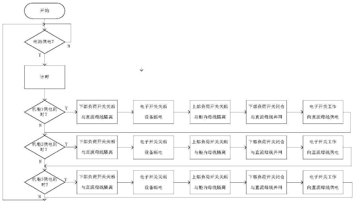
[0061] If the controller detects that the DC bus is in the battery power supply mode, it uses the cooperation between the load switch and the electronic switch to realize the battery energy scheduling of each cabinet.

[0062] The cabinet energy scheduling method specifically includes:

[0063] Step 1, setting the backup time of each cabinet, when ...


PUM


Abstract

The invention discloses a management system for energy dispatching among data machine room cabinets. The management system comprises a plurality of cabinets, a DC bus, a plurality of battery modules,bus and two power distribution units (PDUs), wherein the DC bus is used for connecting the plurality of cabinets, the plurality of battery modules are arranged in each cabinet, each bus is arranged ineach cabinet, each PDU is connected with the buses in the cabinet, a plurality of loads are connected to the PDUs, the plurality of battery modules and the bus in each cabinet are connected by a plurality of first load switches, each battery module is connected to the bus in the cabinet via one of the first load switches, the plurality of battery modules and the DC bus are connected via a plurality of second load switches, each battery module is connected with the DC bus via one of the second load switches, and electronic switches are contained in the battery modules. By the management system, the standby time of each cabinet can be convenient to adjust in a controller, and the battery number of each cabinet is not needed to be adjusted.

Description

technical field [0001] The invention relates to a scheduling management system and method, in particular to a data machine room cabinet energy scheduling management system and method. Background technique [0002] Distributed DC power supply system, as a power supply method for data center, is more and more widely used. The main features of the distributed DC power supply system include that the distributed DC power supply system includes multiple power supply modules distributed on the power supply bus; multiple battery power supply modules distributed on the power supply bus; The load capacity of a single module for full power supply can be low, and the load capacity of the bus is the sum of the load capacity of the individual modules. [0003] Common deployment methods of distributed DC power supply devices include: [0004] 1. Single cabinets are deployed separately and run in a single cabinet; [0005] Advantages: independent power supply, simple management and contr...

Claims


Application Information

Patent Timeline
Patent Type & Authority Patents(China)
IPC IPC(8): H02J9/06H02J7/34H02J13/00
CPCH02J7/34H02J9/06H02J13/0003Y02B70/30Y02B90/20Y04S20/12Y04S20/20Y04S20/248
Inventor 韩旭刘敬伟朱国富崔兵
Owner XIANGJIANG TECH
Learn More