Supercharge Your Innovation With Domain-Expert AI Agents!

Resonant post welding spot height calibration device

A calibration device and resonant column technology, applied in the field of resonant column solder joint height calibration device, can solve the problems of inability to scribe, affect the appearance of the resonant column, inaccurate scribe, etc., and achieve improved appearance and performance, convenient debugging and installation, and reduced cost effect

Inactive Publication Date: 2018-09-18
深圳市金达来精密科技股份有限公司
View PDF8 Cites 4 Cited by
  • Summary
  • Abstract
  • Description
  • Claims
  • Application Information

AI Technical Summary

Problems solved by technology

[0002] In RF devices, the frequency bandwidth of each product is different, and the delay value of the corresponding tap is also different. Usually, the delay value is changed by adjusting the height of the solder joint of the tap. After adjusting the height of the solder joint, it is necessary to adjust the height of the adjusted solder joint. To calibrate, in practice, a caliper is generally used to draw a horizontal line on the resonant column from the bottom of the resonant column to the required height on the resonant column, and then draw a vertical line down the center of the edge of the resonant column, and take two crosses The intersection point is the height of the solder joints; if this method is used to calibrate the height of the solder joints, in the actual operation process, each resonant column needs to measure the marking line by manually operating the vernier caliper, and the production efficiency is extremely low; and the vernier caliper is used to mark the line. During the line process, there will be bad phenomena such as blurring the line due to too light force, drawing a long line when the force is too heavy, or sliding the vernier caliper, and the drawn line is inaccurate, etc., which not only affects the appearance of the resonant column, It also affects the performance of the resonant column in radio frequency devices; in addition, when encountering a resonant column with a reel, the caliper will push against the resonant plate, resulting in the inability to scribe or inaccurate scribe

Method used


Image

  • Resonant post welding spot height calibration device
  • Resonant post welding spot height calibration device
  • Resonant post welding spot height calibration device

Examples


Embodiment Construction

[0025] The present invention will be further described below in conjunction with accompanying drawing:

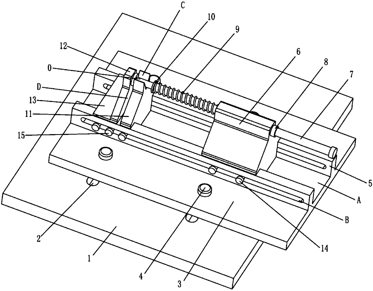
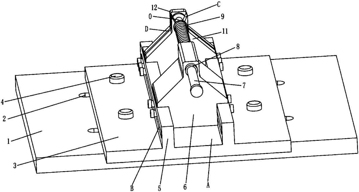
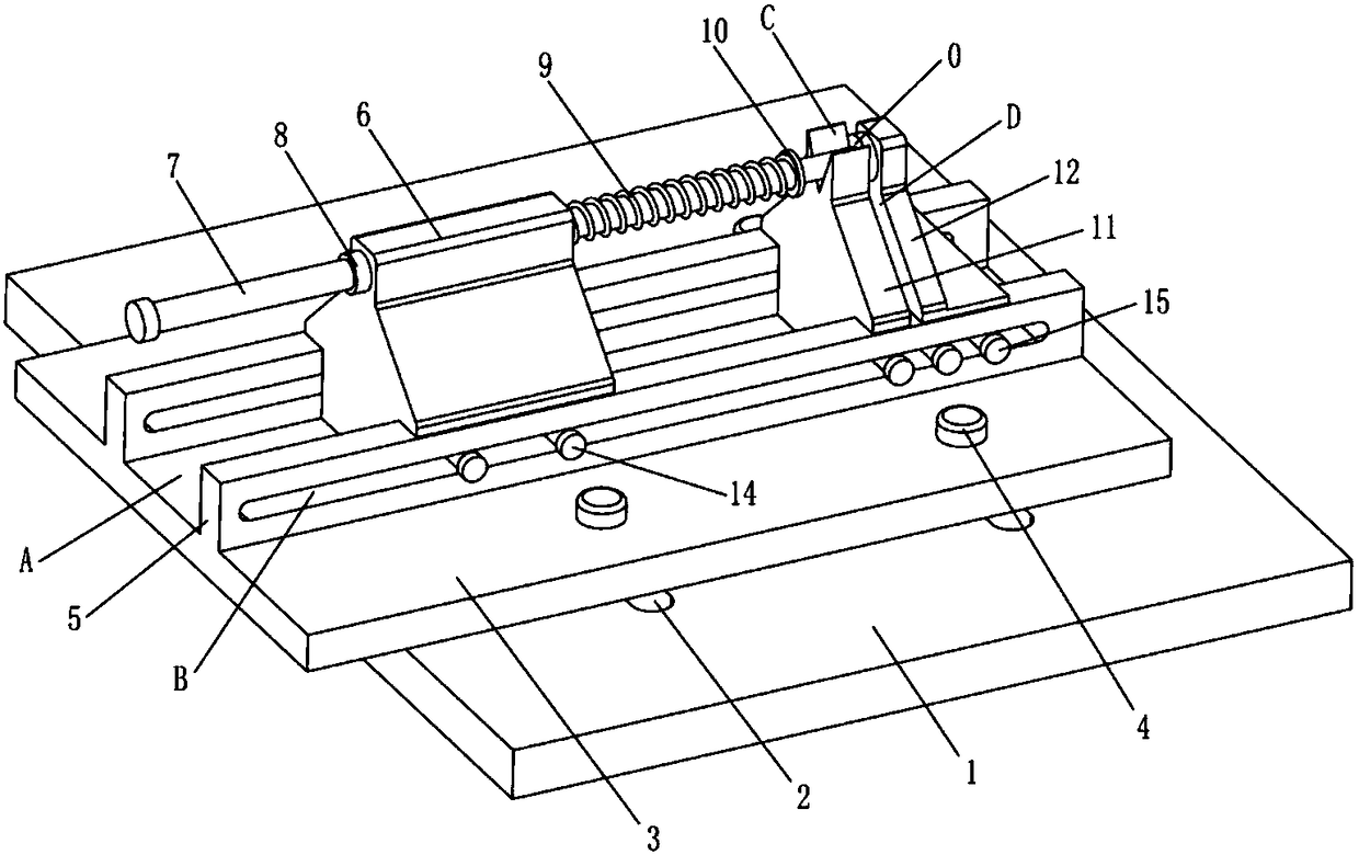
[0026] Such as Figure 1 to Figure 4 As shown, the technical scheme adopted by the present invention is as follows: a device for calibrating the solder joint height of a resonant column, including a base 1, a sliding seat 3, a spring sliding seat 6, a push rod 7, a support 11 and a card seat 12, wherein the above-mentioned base 1 is a rectangular plate structure, the base 1 is set on the machine platform of the bench drill; the above-mentioned sliding seat 3 is set on the base 1, and the sliding seat 3 slides freely along the longitudinal direction on the base 1; There are two guide rails 5 on the ground, and a chute A extending in the transverse direction is formed between the two guide rails 5; the above-mentioned spring slide seat 6 is embedded in the chute A, and slides freely along the chute A; The direction is inserted on the spring sliding seat 6, and the spring 9 i...


PUM


Abstract

The invention discloses a resonant post welding spot height calibration device which comprises a base, a sliding seat, a spring sliding seat, an ejector rod, a support and a clamping seat. The base isof a rectangular platy structure and is arranged on a machine stand of a bench drilling machine; the sliding seat is arranged on the base; two guide rails are arranged on the sliding seat at an interval in parallel along the horizontal direction; a sliding chute extending along the horizontal direction is formed between the two guide rails; the spring sliding seat is embedded into the sliding chute; the ejector rod is inserted onto the spring sliding seat along the horizontal direction; the bottom parts of the support and the clamping seat are connected into a whole and are embedded into thesliding chute; the upper parts of the support and the clamping seat are arranged at an interval along the horizontal direction, and form a clamping groove; a V-shaped groove is formed in the upper part of the support; a resonant post to be height-calibrated is placed in the V-shaped groove along the horizontal direction; and a cap of the resonant post is clamped into the clamping groove along thevertical direction. The resonant post welding spot height calibration device provided by the invention is beneficial to effectively improving the welding spot height positioning accuracy and the appearance of the resonant post, simple in clamping, and high in production efficiency.

Description

technical field [0001] The invention relates to the field of machinery, in particular to a device for calibrating the height of solder joints of resonant columns. Background technique [0002] In RF devices, the frequency bandwidth of each product is different, and the delay value of the corresponding tap is also different. Usually, the delay value is changed by adjusting the height of the solder joint of the tap. After adjusting the height of the solder joint, it is necessary to adjust the height of the adjusted solder joint. To calibrate, in practice, a caliper is generally used to draw a horizontal line on the resonant column from the bottom of the resonant column to the required height on the resonant column, and then draw a vertical line down the center of the edge of the resonant column, and take two crosses The intersection point is the height of the solder joints; if this method is used to calibrate the height of the solder joints, in the actual operation process, ea...

Claims


Application Information

Patent Timeline
IPC IPC(8): B25H7/04
CPCB25H7/04B25H7/045
Inventor 张浩谭膺彤施海兴
Owner 深圳市金达来精密科技股份有限公司
Features
  • R&D
  • Intellectual Property
  • Life Sciences
  • Materials
  • Tech Scout
  • Unparalleled Data Quality
  • Higher Quality Content
  • 60% Fewer Hallucinations
Learn More