
Variable valve timing (VVT) oil supply circuit

An oil circuit and oil supply technology, applied in the direction of engine components, machines/engines, mechanical equipment, etc., can solve the problems of poor VVT response, long time, slow speed, etc., to achieve high oil filling efficiency, fast oil pressure establishment, and improved Responsive Effects

Inactive Publication Date: 2018-09-18
CHONGQING CHANGAN AUTOMOBILE CO LTD
View PDF3 Cites 1 Cited by
  • Summary
  • Abstract
  • Description
  • Claims
  • Application Information

AI Technical Summary

Problems solved by technology

[0003] In the VVT ​​oil supply oil circuit of the existing VVT engine, there is a cylinder head main oil channel, which is divided into the intake side and the exhaust side, and supplies oil to the intake VVT ​​and exhaust VVT. The mutual influence of the oil pressure on the intake side and the oil pressure on the exhaust side and the slow response of VVT
[0004] In addition, in the existing VVT oil supply circuit, the oil control valve controlling VVT adopts plug-in type and is arranged and installed on the cylinder head. It is necessary to arrange multiple oil passages to connect the VVT ​​and the oil control valve to form a control oil circuit, resulting in The direction of the oil circuit has changed direction many times, and the pressure loss of the system increases. When the camshaft phase needs to be adjusted, the VVT ​​adjusts the camshaft phase for a long time and at a slow speed, resulting in poor response of the VVT, thus limiting the performance of the VVT ​​system

Method used


Image

  • Variable valve timing (VVT) oil supply circuit
  • Variable valve timing (VVT) oil supply circuit
  • Variable valve timing (VVT) oil supply circuit

Examples


Embodiment Construction

[0020] The present invention will be described in detail below in conjunction with the accompanying drawings.

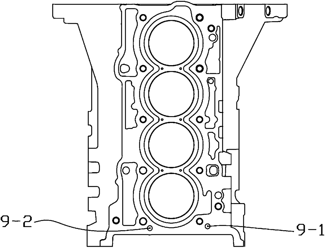
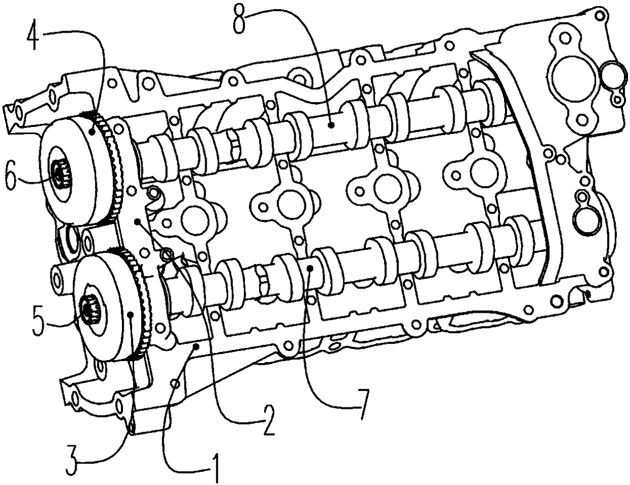
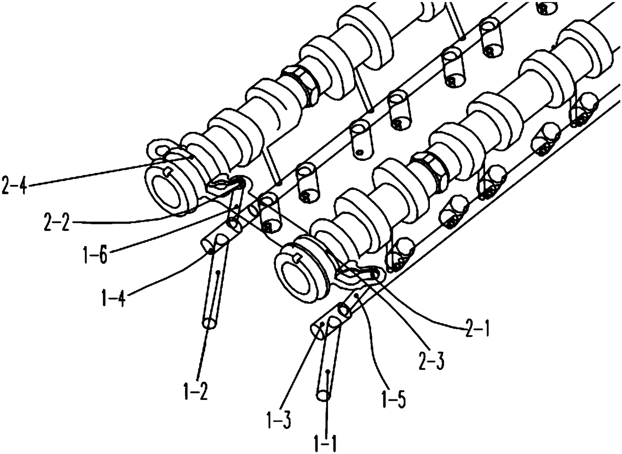
[0021] Such as Figure 1 to Figure 8 The VVT ​​oil supply oil circuit shown includes the intake VVT ​​control oil circuit, the exhaust VVT control oil circuit, the vertical intake main oil passage 1-1 arranged on the cylinder head 1, and the horizontal intake auxiliary oil passage 1-3. Vertical exhaust main oil passage 1-2 and horizontal exhaust auxiliary oil passage 1-4. Intake main oil passage 1-1 is located on the intake side of cylinder head 1. Intake main oil passage 1 One end of -1 communicates with the intake oil passage 9-1 of the cylinder block, and the other end communicates with the auxiliary intake oil passage 1-3 of the cylinder block, leading the engine oil in the intake oil passage 9-1 of the cylinder block to the cylinder head 1, and discharging The air main oil passage 1-2 is located on the exhaust side of the cylinder head 1, one end of the exhaust...


PUM


Abstract

The invention discloses a variable valve timing (VVT) oil supply circuit which comprises an air inlet VVT control oil circuit, an exhaust VVT control oil circuit, and an air inlet main oil channel, anair inlet auxiliary oil channel, an exhaust main oil channel and an exhaust auxiliary oil channel arranged on a cylinder cover. One end of the air inlet main oil channel communicates with an air inlet oil channel of a cylinder body; the other end of the air inlet main oil channel communicates with the air inlet auxiliary oil channel; the air inlet auxiliary oil channel communicates with the air inlet VVT control oil circuit; one end of the exhaust main oil channel communicates with an exhaust oil channel of the cylinder body; the other end of the exhaust main oil channel communicates with theexhaust auxiliary oil channel; and the exhaust auxiliary oil channel communicates with the exhaust VVT control oil circuit. According to the oil circuit, an interaction effect of oil pressure at theair inlet side and oil pressure at the exhaust side can be avoided, and the responsiveness of VVT is ensured.

Description

technical field [0001] The invention belongs to the technical field of automobile engines, and in particular relates to a VVT oil supply oil circuit. Background technique [0002] In order to meet the increasingly stringent requirements of engines in terms of power, economy and emissions, engine upgrades are urgently needed, and more and more new technologies (such as VVT, variable valve timing) are applied to automobile engines and promote. VVT technology can improve engine power, fuel economy and meet new emission regulations. [0003] In the VVT ​​oil supply oil circuit of the existing VVT engine, there is a cylinder head main oil channel, which is divided into the intake side and the exhaust side, and supplies oil to the intake VVT ​​and exhaust VVT. The oil pressure on the intake side and the oil pressure on the exhaust side affect each other and the VVT ​​response is slow. [0004] In addition, in the existing VVT oil supply circuit, the oil control valve controllin...

Claims


Application Information

Patent Timeline
Patent Type & Authority Applications(China)
IPC IPC(8): F01L1/344
CPCF01L1/3442F01L2001/34426
Inventor 司莉纳谢宗让王茂辉张云富韦颂
Owner CHONGQING CHANGAN AUTOMOBILE CO LTD
Learn More