A double rocking multi-position steady support ball valve
What is Al technical title?
Al technical title is built by PatSnap Al team. It summarizes the technical point description of the patent document.
A multi-position, ball-supporting technology, applied in valve details, valve device, valve operation/release device, etc., can solve the problems of inflexible closing, valve seat system failure, poor stability of the pressing link, etc., and achieve a compact structure. Stable, reduced parts, good preload performance
Active Publication Date: 2019-07-16
CHANGSHA UNIVERSITY OF SCIENCE AND TECHNOLOGY
View PDF6 Cites 0 Cited by
Summary
Abstract
Description
Claims
Application Information
AI Technical Summary
This helps you quickly interpret patents by identifying the three key elements:
Problems solved by technology
Method used
Benefits of technology
Problems solved by technology
[0004] 1. Ball valves in the prior art, especially large ball valves, are inflexible and bulky when closing, and are likely to cause strong water hammer. Multiple opening and closing have an impact on the service life of related accessories
[0005] 2. Ball valves in the prior art, especially large ball valves, are difficult to achieve flexible gear adjustment and have a single function
[0006] 3. Ball valves in the prior art, especially large ball valves, contain too many parts and are not compact in structure. For this, a small amount of prior art provides a compensation and preloading scheme for the spring valve seat, but this scheme leads to more and more parts. Miscellaneous, in case of spring failure, it will cause the entire valve seat system to fail, resulting in an accident
[0007] 4. The ball valve in the prior art uses an integrated valve seat, which has a single function, poor fault tolerance and inclusiveness, and becomes invalid after wear and tear
[0008] 5. A small amount of pressure rings are used in the ball valves of the prior art to adjust the pre-tightening of the valve seat. However, due to the large number of parts, and the pressure ring is pressed by the pressure plate, the pressure ring is pressed against the seat, and the stability of the compression link is poor.
[0009] 6. The ball valves in the prior art have adjustment and preload compensation in the horizontal direction, but lack vertical adjustment and preload compensation.
Method used
Image
Click on the blue label to locate the original text in one second.
Reading with bidirectional positioning of images and text.
Examples
Embodiment Construction
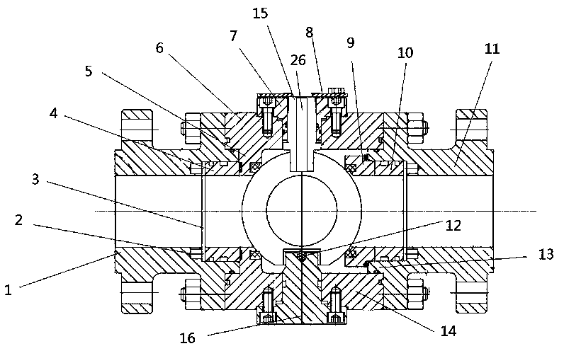
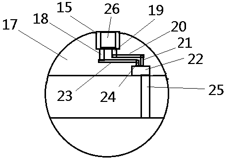
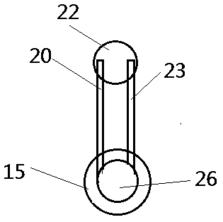
[0034] As shown in the figure: a double rocking multi-position stable support ball valve, including a left flange, a pretensioner, a spacer ring, a left pressure ring, a convex valve seat, an upper valve body, a shaft sleeve, a connecting plate, and a right valve seat , right pressure ring, pressure plate flange, lower spring, left protrusion, lower valve body, outer valve stem, lower valve shaft, ball, first long rod, first short rod, upper connecting rod, second long rod, Secondary shaft, lower connecting rod, second short rod, auxiliary valve plate, inner valve stem; the left flange is located on the left side of the upper and lower valve bodies, and the pressure plate flange is located on the right side of the upper and lower valve bodies, The shaft sleeve is fixed on the upper side of the upper valve body by screws, and the connecting plate is fixed on the upper side of the shaft sleeve to connect the driving device. There is a through hole in the shaft sleeve, and the out...
PUM
Abstract
The invention discloses a multi-gear steady-supporting ball valve controlled by a double rocker. The multi-gear steady-supporting ball valve comprises a left flange, a pre-tightening piece, a separation ring, a left pressing ring, a lower convex valve seat, an upper valve body, a shaft sleeve, a connecting plate, a right valve seat, a right pressing ring, a pressing plate flange, a lower spring, aleft protruding part, a lower valve body, an outer valve rod, a lower valve shaft, a ball body, a first long rod, a first short rod, an upper connecting rod, a second long rod, an auxiliary shaft, alower connecting rod, a second short rod, an auxiliary valve plate and an inner valve rod, wherein the inner valve rod is arranged in the outer valve rod, the first long rod and the first short rod are arranged at the lower end of the inner valve rod, the tail end of the first long rod is connected with the lower connecting rod, the tail end of the first short rod is connected with the upper connecting rod, the other end of the upper connecting rod is connected with the top end of the second long rod, and the other end of the lower connecting rod is connected with the top end of the second short rod; and the upper connecting rod and the lower connecting rod are located on different horizontal planes and do not interfere with each other, the lower end of the second long rod is connected with the auxiliary valve plate, and the lower end of the second short rod is connected with the auxiliary valve plate. The multi-gear steady-supporting ball valve is characterized in that the inner valverod rotates to drive the first long rod and the first short rod to rotate so as to drive the second long rod and the second short rod to rotate, and therefore the auxiliary valve plate can be drivento be opened and closed, and the auxiliary valve plate is screwed into the ball body when opened; and a groove for containing the auxiliary valve plate in the ball body is formed by injection molding.
Description
technical field [0001] The invention relates to the related fields of fluid control, in particular to a double rocking, multi-gear and stable support ball valve. Background technique [0002] The hydraulic cylinder execution system is a commonly used execution system, which controls the reciprocating motion of the hydraulic cylinder through the main hydraulic drive circuit and the hydraulic drive branch circuit for driving. Ball valves are common components among them. [0003] In actual use, the ball valves in the existing execution system have the following problems: [0004] 1. Ball valves in the prior art, especially large ball valves, are inflexible and bulky when closing, and are likely to cause strong water hammer, and multiple opening and closing have an impact on the service life of related accessories. [0005] 2. Ball valves in the prior art, especially large ball valves, are difficult to realize flexible gear adjustment and have single functions. [0006] 3. B...
Claims
Application Information
Patent Timeline
Application Date:The date an application was filed.
Publication Date:The date a patent or application was officially published.
First Publication Date:The earliest publication date of a patent with the same application number.
Issue Date:Publication date of the patent grant document.
PCT Entry Date:The Entry date of PCT National Phase.
Estimated Expiry Date:The statutory expiry date of a patent right according to the Patent Law, and it is the longest term of protection that the patent right can achieve without the termination of the patent right due to other reasons(Term extension factor has been taken into account ).
Invalid Date:Actual expiry date is based on effective date or publication date of legal transaction data of invalid patent.
Patent Type & Authority Patents(China)
IPC IPC(8): F16K31/44F16K5/08F16K5/06F16K5/10
CPCF16K5/06F16K5/08F16K5/10F16K31/44
Inventor 李微左炉李聪李传常何建军陈建林邱玮任延杰
Owner CHANGSHA UNIVERSITY OF SCIENCE AND TECHNOLOGY