Cupboard lamp

A lamp and cabinet technology, applied in the field of cabinet lamps, can solve the problems of hands being occupied, waste of resources, low heat generation, etc.

Pending Publication Date: 2018-09-18
周勇涛
View PDF8 Cites 0 Cited by
  • Summary
  • Abstract
  • Description
  • Claims
  • Application Information

AI Technical Summary

Problems solved by technology

[0002] LED light source has the advantages of high luminous efficiency, low heat generation, power saving and long life, so its application is becoming more and more extensive. LED lamps gradually replace traditional lighting lamps. Cabinets are used to store kitchen utensils. When it is necessary to take out the tableware in the cabinet At this time, it is necessary to turn on the lamps in the cabinet. When the user takes out the tableware, his hands may be occupied. He needs to put down the tableware before turning off the lamps. Sometimes he forgets to turn off the switch, resulting in a waste of resources. Cabinet Lighting

Method used


Image

  • Cupboard lamp
  • Cupboard lamp
  • Cupboard lamp

Examples


Embodiment Construction

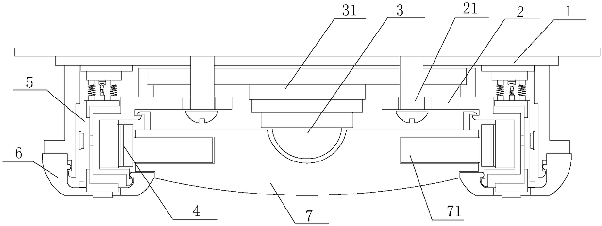
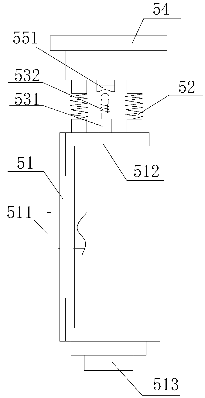
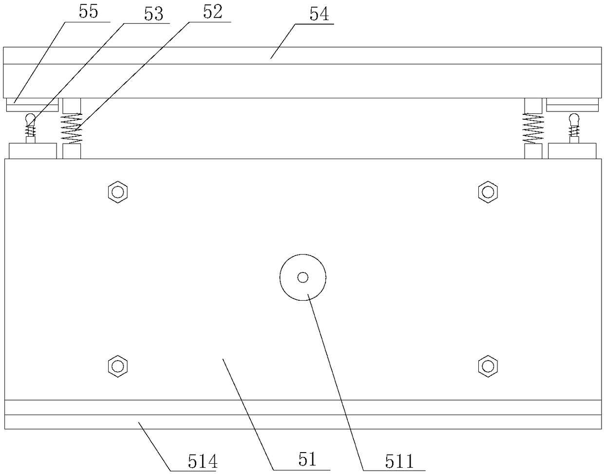
[0017] refer to Figure 1 to Figure 4 A cabinet lamp of the present invention comprises a lamp base 1, an installation support frame 2, an LED lamp assembly 3, an LED side lamp assembly 4, a side lamp trigger assembly 5, a second lampshade 6 and a first lampshade 7, the lamp base 1 is provided with an LED light assembly 3 at the center, and a first lampshade 7 is provided directly below the LED light assembly 3. Both sides of the LED light assembly 3 are symmetrically provided with an installation support frame 2, and the installation support frame 2 The bolt assembly 21 is fixed under the lamp base 1, the inside of the installation support frame 2 is provided with an installation cavity, the installation cavity is provided with an LED side light assembly 4, and the outside of the installation support frame 2 is provided with a side The light trigger assembly 5, the side light trigger assembly 5 is used to control the switch of the LED side light assembly 4, the side light tri...


PUM


Abstract

The invention discloses a cupboard lamp. The cupboard lamp comprises a lamp pedestal, mounting supporting frames, an LED lamp assembly, LED side lamp assemblies, side lamp trigger assemblies, a secondlampshade and a first lampshade, wherein the LED lamp assembly is arranged on the center of the lamp pedestal; the first lampshade is arranged below the LED lamp assembly; the mounting supporting frames are symmetrically arranged at the two sides of the LED lamp assembly; the mounting supporting frames are fixedly arranged below the lamp pedestal through bolt assemblies; mounting cavities are arranged at the inner sides of the mounting supporting frames; the LED side lamp assemblies are arranged in the mounting cavities; the side lamp trigger assemblies are arranged at the outer sides of themounting supporting frames; the side lamp trigger assemblies are used for controlling on and off of the LED side lamp assemblies; the second lampshade is arranged below the LED side lamp assemblies; light-emitting parts are separately mounted on the center and the two sides of the lamp; a central LED lamp is controlled to turn on and off through a switch; side lamp assemblies control the switch through the side lamp trigger assemblies; and a swing frame returns to control side lamps to automatically turn off.

Description

【Technical field】 [0001] The invention relates to the technical field of LED lamps, in particular to a cabinet lamp. 【Background technique】 [0002] LED light source has the advantages of high luminous efficiency, low heat generation, power saving and long life, so its application is becoming more and more extensive. LED lamps gradually replace traditional lighting lamps. Cabinets are used to store kitchen utensils. When it is necessary to take out the tableware in the cabinet At this time, it is necessary to turn on the lamps in the cabinet. When the user takes out the tableware, his hands may be occupied. He needs to put down the tableware before turning off the lamps. Sometimes he forgets to turn off the switch, resulting in a waste of resources. Kind of cabinet lamps. 【Content of invention】 [0003] The purpose of the present invention is to solve the problems in the prior art, and propose a cabinet lamp. By installing light-emitting parts on the center and both sides...

Claims


Application Information

Patent Timeline
Patent Type & Authority Applications(China)
IPC IPC(8): F21S8/00F21V17/16F21V19/00F21V23/04F21Y115/10
CPCF21S8/00F21V17/164F21V19/001F21V23/003F21V23/04F21Y2115/10
Inventor 周勇涛胡威严成雯豪黄纪秋吴杰张云云
Owner 周勇涛
Why Eureka
Try Eureka