
Deformation buffer type emergency brake device for elevator

An emergency braking and elevator technology, used in transportation, packaging, elevators, etc., can solve the problems of unstable braking, poor adaptability, elevator accidents, etc., and achieve a reasonable and compact structure design, strong installation adaptability, and high safety. Effect

Inactive Publication Date: 2018-09-21
景晓冬
View PDF4 Cites 7 Cited by
  • Summary
  • Abstract
  • Description
  • Claims
  • Application Information

AI Technical Summary

Problems solved by technology

[0002] With the continuous improvement of the height of the building, the penetration rate of elevators is getting higher and higher, and the problems in the operation of elevators are becoming more and more obvious. The most dangerous failure of elevators is the failure of falling. The traditional emergency braking mechanism, in To deal with such problems, a single braking structure is often used, resulting in problems such as poor braking effect, unstable braking, and poor adaptability.
[0003] In order to solve the above problems, the present invention is proposed, which overcomes the problems of the traditional elevator emergency braking device, such as the use of a reverse offset braking structure, which causes a large braking load, the braking device is prone to failure, and elevator accidents, etc., and solves the problem Due to the use of a single shock-absorbing and buffering structure in the traditional elevator emergency braking device, the effect is poor in the braking and buffering of high-rise elevator failures. Good braking buffer effect, high safety and other advantages

Method used


Image

  • Deformation buffer type emergency brake device for elevator
  • Deformation buffer type emergency brake device for elevator
  • Deformation buffer type emergency brake device for elevator

Examples


Embodiment Construction

[0018] The technical solutions in the embodiments of the present invention will be clearly and completely described below in conjunction with the accompanying drawings in the embodiments of the present invention. Obviously, the described embodiments are only a part of the embodiments of the present invention, rather than all the embodiments. Based on the embodiments of the present invention, all other embodiments obtained by those of ordinary skill in the art without creative work shall fall within the protection scope of the present invention.

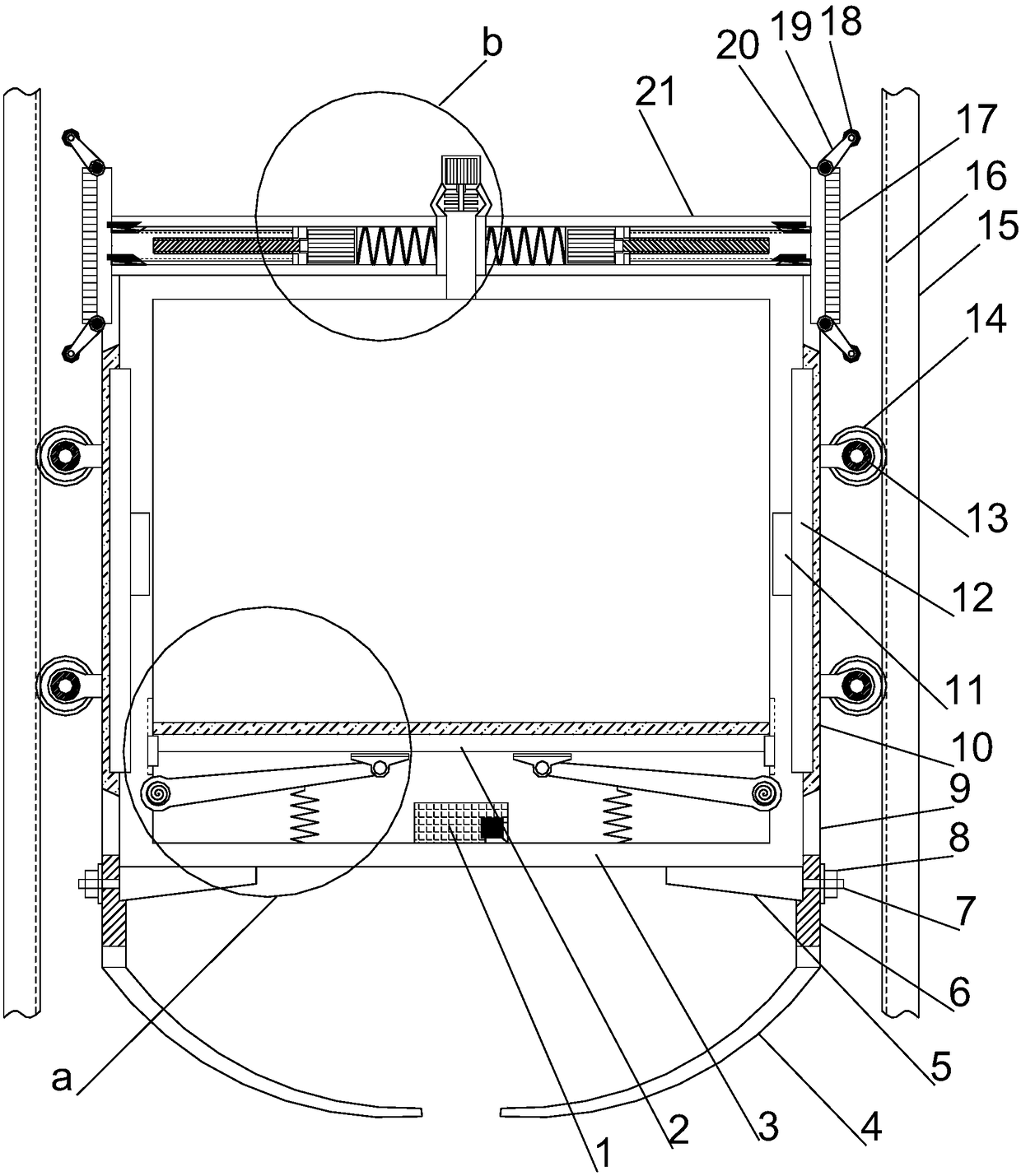
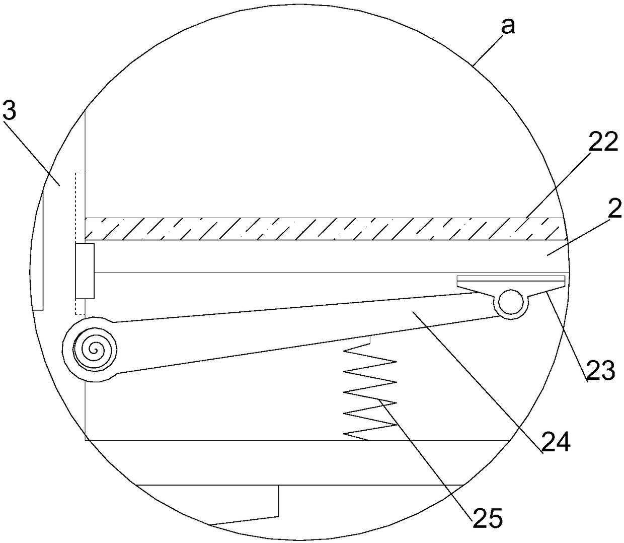
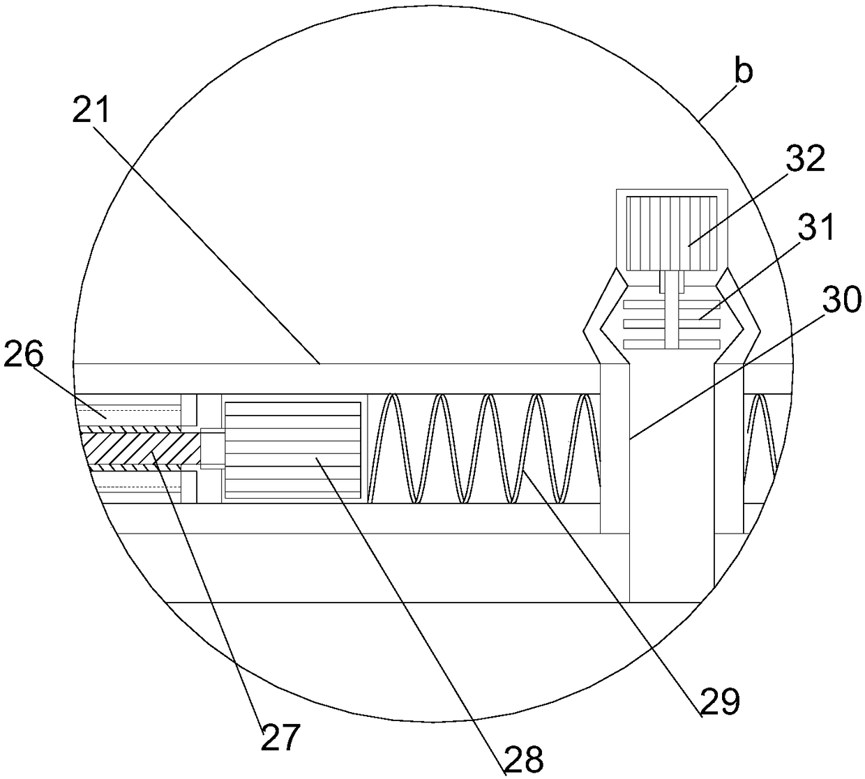
[0019] See Figure 1~4 In the embodiment of the present invention, a deformation buffer type elevator emergency braking device includes a vertically arranged elevator installation frame 3, and an emergency braking buffer module is arranged vertically on the outer side of the elevator installation frame 3. The brake buffer module includes a buffer mounting tube 9 vertically arranged on the outside of the elevator mounting frame 3. The upp...


PUM


Abstract

The invention discloses a deformation buffer type emergency brake device for an elevator. The deformation buffer type emergency brake device comprises a vertically arranged elevator mounting frame andis characterized in that an emergency brake buffer module is vertically arranged outside the elevator mounting frame in a wrapping manner, the emergency brake buffer module comprises a buffer mounting cylinder vertically arranged outside the elevator mounting frame, a brake mounting plate coordinated with the elevator mounting frame is horizontally arranged at the upper end of the buffer mountingcylinder, a vertical and downward through ventilation hole is formed in the middle of the brake mounting plate, telescoping squeezing brake structures are embedded into the brake mounting plate partson the left side and the right side of the ventilation hole in a left-right symmetry manner, each telescoping squeezing brake structure comprises a guide mounting hole extending out from the interiorof the brake mounting plate, and a guide inner threaded cylinder is horizontally arranged inside each guide mounting hole. The deformation buffer type emergency brake device is reasonable and compactin structural design, high in mounting adaptability, good in brake buffer effect by combining active and passive brake buffer, high in safety and the like.

Description

Technical field [0001] The invention relates to the field of elevator safety, in particular to a deformation buffer type elevator emergency braking device. Background technique [0002] With the continuous improvement of the height of buildings, the popularity of elevators is getting higher and higher, and the problems that appear in the operation of elevators are becoming more and more obvious. The most dangerous of the elevator failures is the fall failure. The traditional emergency braking mechanism To deal with such problems, a single braking structure is often used, which causes problems such as poor braking effect, unstable braking, and poor adaptability. [0003] In order to solve the above-mentioned problems, the present invention is proposed, which overcomes the problems of traditional elevator emergency braking devices. Due to the reverse offset braking structure, the braking load is large, the braking device is prone to failure, and elevator accidents. The traditional e...

Claims


Application Information

Patent Timeline
Patent Type & Authority Applications(China)
IPC IPC(8): B66B5/04B66B5/18B66B5/28
CPCB66B5/04B66B5/18B66B5/284
Inventor 景晓冬罗丹李敏
Owner 景晓冬
Learn More