
Novel rotatable medical patch board

A plug-in board, a new type of technology, applied in the direction of flexible lead wire devices, medical/surgical connectors, etc., can solve the problems of prone to accidents, inconvenient long-term use, and many thread ends, so as to achieve convenient use, easy operation and use, and save space effect of position

Inactive Publication Date: 2018-09-21
国药集团四川省川南医疗器械有限公司
View PDF4 Cites 2 Cited by
  • Summary
  • Abstract
  • Description
  • Claims
  • Application Information

AI Technical Summary

Problems solved by technology

[0004] The technical problem to be solved by the present invention is that when the existing medical plugs are used, there are many and long thread ends, accidents are prone to occur in panic, and it is not convenient for long-term use. Problems with the use of plugboards

Method used


Image

  • Novel rotatable medical patch board
  • Novel rotatable medical patch board

Examples


Embodiment 1

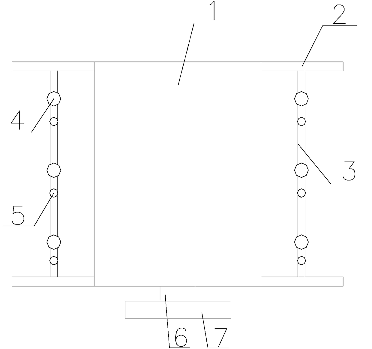
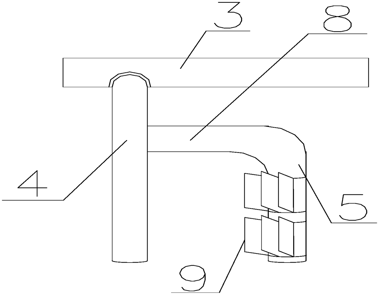
[0023] Such as figure 1 and figure 2 As shown, a new rotatable medical plugboard of the present invention includes a plugboard 1 and a plug-in wire. The two opposite sides of the plugboard 1 are connected with take-up devices. Two connecting rods 2 parallel to each other at the end, a support rod 3 connected between the two connecting rods 2, a number of wire take-ups are connected to the support rod 3, and the wire take-up device includes a rotating rod 4 vertically connected to the support rod 3 , one end vertically connected to the horizontal connecting rod 8 on the rotating rod 4 and the rotating rod 5 vertically connected to the other end of the connecting rod 8, the rotating rod 4 can drive the rotating rod 5 to rotate on the support rod 3; the rotating rod 5 and the rotating rod 4 are parallel to each other and the distance between them is 1cm. The connecting rod 2 is provided with a control button for controlling the rotation of the rotating rod 4. When the plug-in w...

Embodiment 2

[0025] A new type of rotatable medical insert, on the basis of Embodiment 1, several baffles 9 are arranged on the rotary rod 5, the baffles 9 are rubber materials, and the shape of the baffles 9 is a cube with a length of 1 mm. The connecting rod 2 is connected to the side of the plug-in board 1 through buckles. There are at least three wire take-ups on the support rod 3, and the connecting rod 2 is provided with control buttons for respectively controlling the rotation of the rotating rod 4 on each wire take-up.

Embodiment 3

[0027] A new type of rotatable medical flashboard, on the basis of Embodiment 1, the lower end of the flashboard 1 is provided with a telescopic telescopic rod 6, and the other end of the telescopic rod 6 is provided with a support plate 7 for supporting the flashboard 1.


PUM


Abstract

The invention discloses a novel rotatable medical patch board. Two opposite sides of the patch board are connected to wire take-up devices. Each of the wire take-up devices comprises two parallel connecting rods connected to two ends of the patch board and a support rod connected between the two connecting rods. The support rod is connected to a plurality of wire take-up apparatuses, each of the wire take-up apparatuses comprises a rotating rod vertically connected to the support rod, a horizontal connection rod whose one end is vertically connected to the rotating rod, and a rotation rod which is vertically connected to the other end of the connection rod, and the rotating rod drives the rotation rod to rotate on the support rod. The rotation rods and the rotating rods are parallel to each other with the distance of 1cm, the connecting rods are provided with control buttons for controlling the rotating rods to rotate, when a plug wire is inserted into the patch board, a wire in the plug wire is located between a rotation rod and a rotating rod, and the wire is wound around the rotation rod and the rotating rod when the rotation rod and the rotating rod rotate. The novel rotatablemedical patch board has a simple structure and is convenient to operate and use.

Description

technical field [0001] The invention relates to the field of plugs, in particular to a novel rotatable medical insert. Background technique [0002] Connectors are generally divided into two halves, a plug and a socket. The plug generally refers to the half that is not fixed. A plug refers to a movable joint that is connected to a device that uses electricity through a wire; while a socket is fixed on a device or a building structure. Plugs usually have protruding rod-shaped, blade-shaped, etc. electrical contacts (called male connectors), while sockets have correspondingly shaped electrical contact slots (called female connectors). Power sockets and plugs vary in appearance, grade, size and type according to different countries and regions; each country has standards formulated by the government. If the size of the plug is unqualified, it will affect the user's use or cause hidden dangers such as poor contact and mis-insertion. In the slightest, the equipment will be dam...

Claims


Application Information

Patent Timeline
Patent Type & Authority Applications(China)
IPC IPC(8): H01R13/72
CPCH01R13/72H01R2201/12
Inventor 张明华
Owner 国药集团四川省川南医疗器械有限公司
Learn More