5G test shielding box
A shielding box and 5G technology, applied in the fields of magnetic field/electric field shielding, antenna support/installation device, electrical components, etc., can solve the problems of incompatibility with test frequency, inability to guarantee accurate testing of fifth-generation mobile communication products, etc., and achieve improvement Test accuracy, improve shielding performance, and high test accuracy
- Summary
- Abstract
- Description
- Claims
- Application Information
AI Technical Summary
Problems solved by technology
Method used
Image

Examples
Embodiment 1
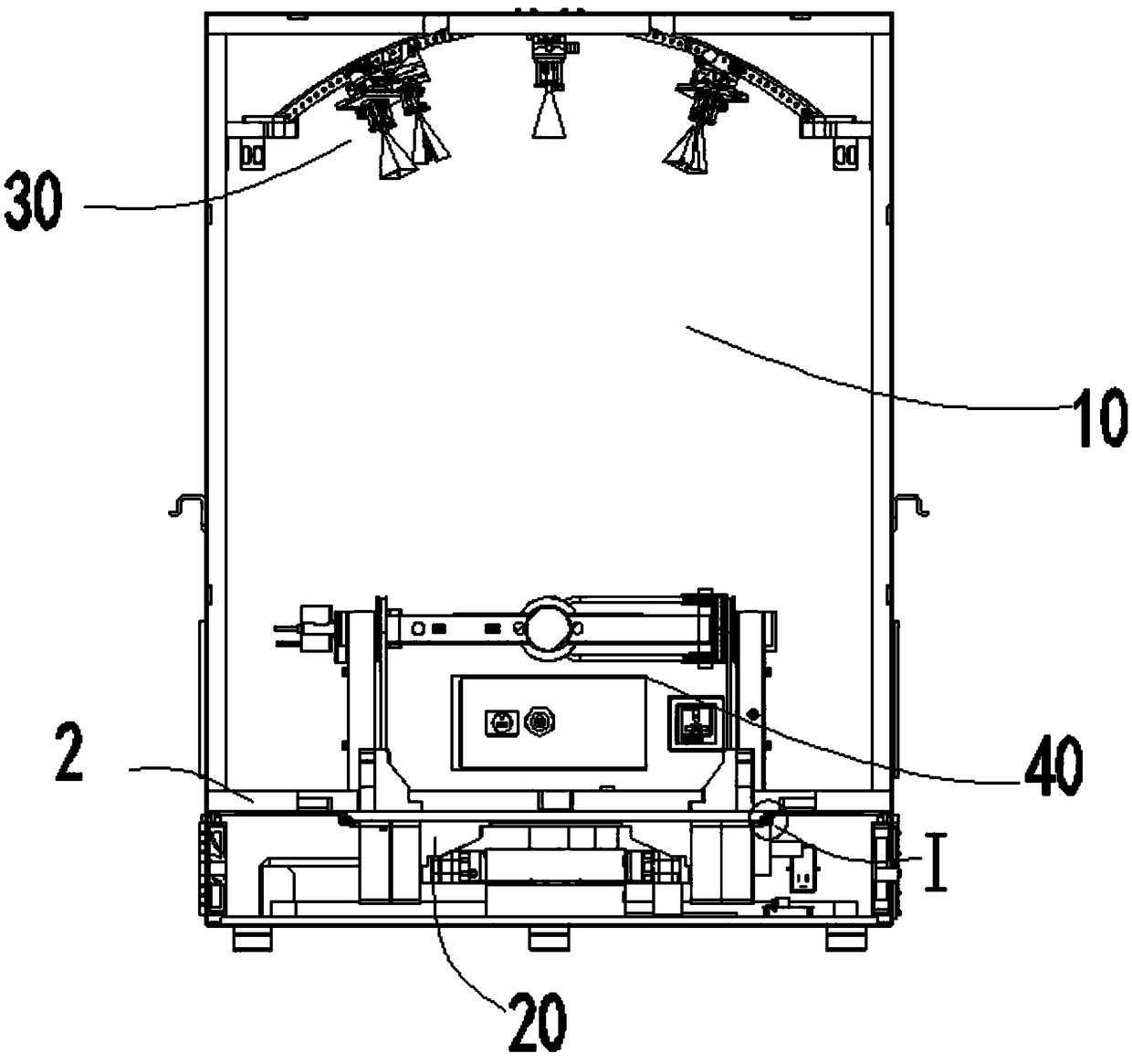
[0025] The antenna supports 36 are provided in four groups, and the antenna supports are evenly distributed on the antenna panel 31; each group of antenna supports is provided with an antenna module 7 correspondingly, and the antenna modules 7 are installed symmetrically with respect to the antenna panel. Symmetrical installation is convenient for adjusting the installation position of the antenna module.
[0026] The antenna bracket is an arc-shaped bracket, and the antenna module mounting structure 32 is a mounting hole. It should be noted that the antenna module mounting structure 32 is not limited to mounting holes and other forms, such as buckles, etc.; any mounting structure capable of fixing the antenna module at any position on the antenna support belongs to the protection scope of the present invention.
[0027] The connection between the antenna module 7 and the product under test on the carrier board assembly constitutes a first connection, and the connection between the...
Embodiment 2
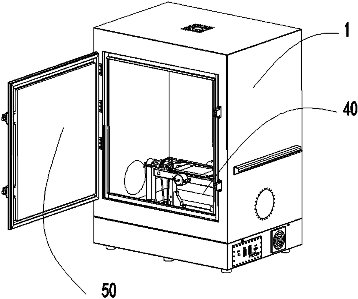
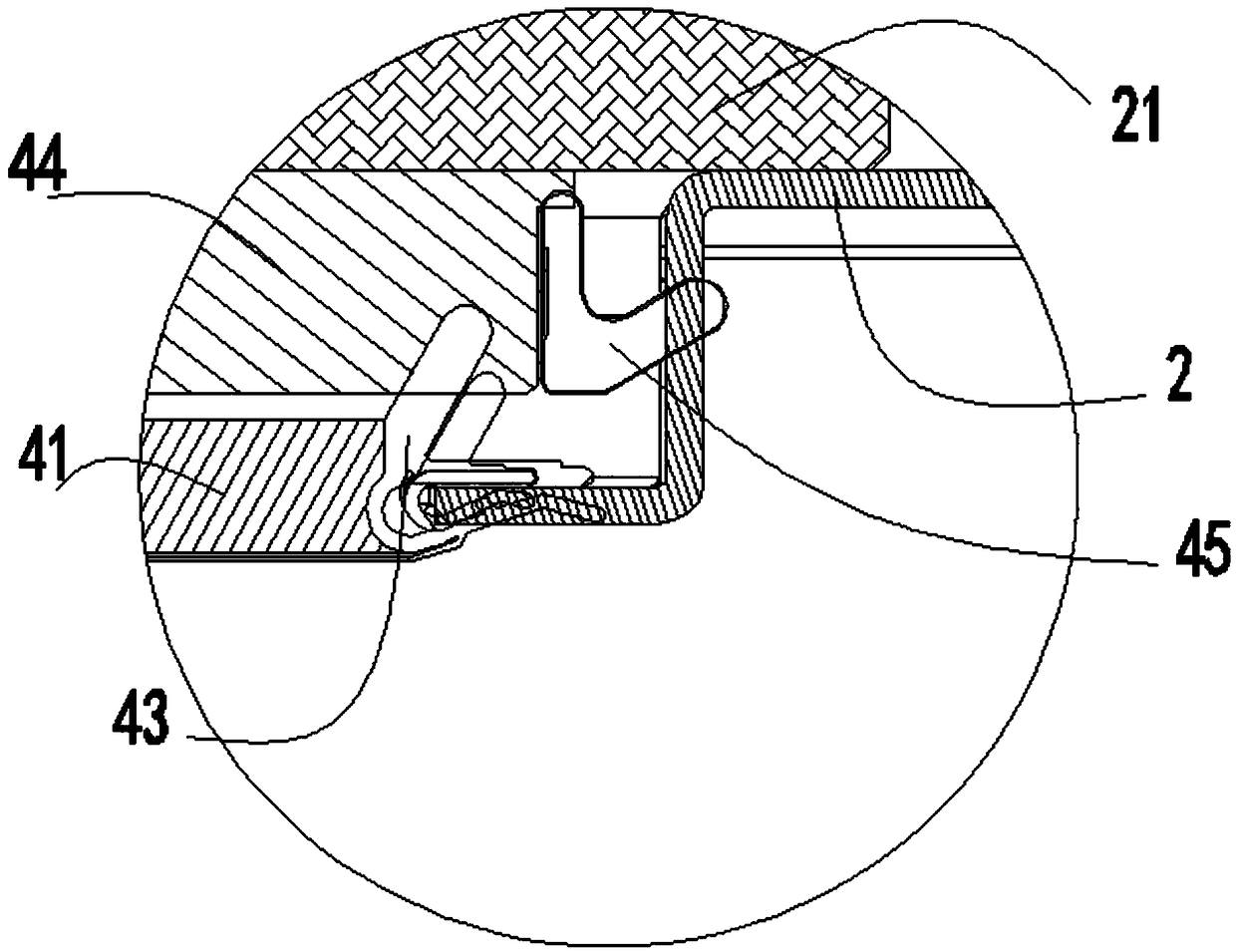
[0031] The test cavity 10 is provided with a door body 50, and the joint between the door body and the box body is provided with a concave-convex sealing structure. The concave-convex sealing structure includes a convex door structure, a concave box structure, and a sealing material. The convex structure of the door matches the concave structure of the box, and the convex structure of the door matches the concave structure of the box. Shielding material 8 is provided between. In addition, the edge 52 of the convex structure of the door and the edge 11 of the concave structure of the box are both provided with a D-shaped shielding material 53 / 12, which further reduces the leakage at the junction of the door and the box.
[0032] Among them, the door and the box body are matched in a 110° way, and the shielding materials in three directions (shielding material 8, D-shaped shielding material 53 / 12) are pressed together, and the leakage at the junction of the door and the box is the ...
Embodiment 3
[0036] The side wall of the box body is provided with a slidable component in the vertical direction; the antenna support is a telescopic support, one end of the telescopic support is hinged to the antenna panel, and the other end of the telescopic support is hinged to the antenna panel The slidable component. This design can change the tilt angle of the antenna support well to meet different test requirements.
PUM
 Abstract
Description
Claims
Application Information
 - R&D
- Intellectual Property
- Life Sciences
- Materials
- Tech Scout
- Unparalleled Data Quality
- Higher Quality Content
- 60% Fewer Hallucinations
Browse by: Latest US Patents, China's latest patents, Technical Efficacy Thesaurus, Application Domain, Technology Topic, Popular Technical Reports.
© 2025 PatSnap. All rights reserved.Legal|Privacy policy|Modern Slavery Act Transparency Statement|Sitemap|About US| Contact US: help@patsnap.com