
Swing construction method for bridge and swing bridge system

A construction method and swivel technology, applied in the direction of bridges, bridge construction, erection/assembly of bridges, etc., can solve the problems of unbalance, high risk, complicated construction, etc., and achieve the effect of convenient installation, strong safety, and close coordination.

Inactive Publication Date: 2018-09-25
NO 2 ENG CO LTD OF CHINA RAILWAY CONSTR 11 BUREAU GRP +1
View PDF3 Cites 2 Cited by
  • Summary
  • Abstract
  • Description
  • Claims
  • Application Information

AI Technical Summary

Problems solved by technology

[0003] The inventor found that when the weight difference between the two ends of the spherical hinge fulcrum of the swivel bridge is too large, the balance of the swivel cannot be satisfied by only relying on the counterweight at the end of the short arm. At this time, it is an extremely unbalanced swivel construction. High risk and complex construction

Method used


Image

  • Swing construction method for bridge and swing bridge system
  • Swing construction method for bridge and swing bridge system

Examples


no. 1 example

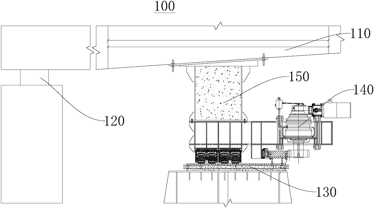
[0032] Please refer to figure 1 , the embodiment of the present invention provides a swivel bridge system 100, which is used for performing swivel movements, thereby completing the construction of the swivel bridge. It is closely matched, stable and reliable, and can stably complete the swivel action when the weight difference between the two ends of the swivel bridge is too large, which is practical, efficient, and safe. The swivel bridge system 100 includes a swivel section 110 , a swivel ball joint 120 , a support rail 130 , a driving device 140 and a front support 150 . The front support 150 and the swivel spherical hinge 120 are arranged at intervals, and both are connected with the swivel section 110 . Driven by the front support 150 , the swivel section 110 can rotate around the swivel spherical hinge 120 to complete the swivel action. The position of the supporting rail 130 is fixed, and the driving device 140 cooperates with the supporting rail 130 so that the drivi...

no. 2 example

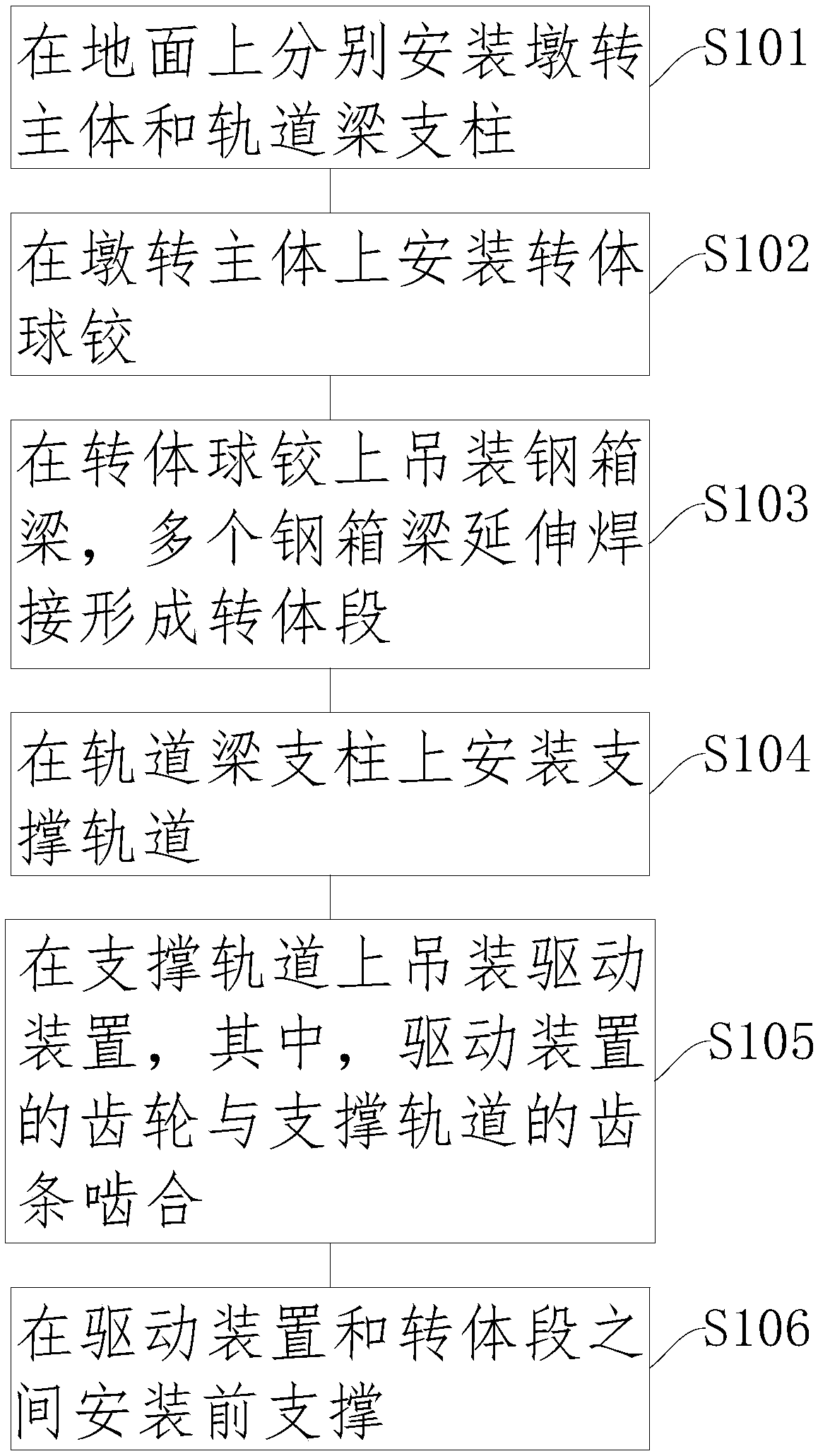
[0036] Please refer to figure 2 , an embodiment of the present invention provides a bridge swivel construction method for constructing a swivel bridge system 100 . It can produce a swivel bridge system 100 that is closely matched, stable and reliable, can stably complete the swivel action when the weight difference between the two ends of the swivel bridge is too large, is practical, efficient, and safe. The swivel bridge system 100 is used for swivel action, thereby completing the construction of the swivel bridge.

[0037] The bridge swivel construction method includes the following steps:

[0038] Step S101: install the main body of the pier and the support of the track beam on the ground respectively.

[0039] It is worth noting that in this step, the construction and installation of the main body of the pier and the track beam pillars can be carried out at the same time or in steps, and the construction sequence of the main body of the pier and the track beam pillars i...


PUM


Abstract

The invention discloses a swing construction method for a bridge and a swing bridge system, and relates to the technical field of bridge swing. The method comprises the following steps: a pier swing main body and track beam stanchions are mounted on the ground respectively; a swing spherical hinge is mounted on the pier swing main body; steel box girders are hoisted on the swing spherical hinge, and multiple steel box girders extend and are welded to form a swing section; a support track is mounted on the track beam stanchions; a drive device is hoisted onto the support track, and a gear of the drive device is meshed with a rack of the support track; a front support is mouthed between the drive device and the swing section. Compared with the prior art, the swing construction method for thebridge adopts the steps of mounting the support track on the track beam stanchions and hoisting the drive device onto the support track, so that the swing bridge system which is close in coordination, firm, reliable, practical, efficient, high in safety and capable of swinging stably when the swing weight difference of two ends of the swing bridge is too large can be produced.

Description

technical field [0001] The invention relates to the technical field of bridge swivels, in particular to a bridge swivel construction method and a swivel bridge system. Background technique [0002] A swivel bridge is a bridge constructed using the swivel method. Bridge swivel construction refers to a construction method in which the bridge structure is formed (cast or spliced) at a position other than the design axis, and then put in place by swivel. It converts operations over obstacles to operations onshore or near the surface. According to the rotation direction of the bridge structure, it can be divided into vertical rotation construction method, horizontal rotation construction method (referred to as vertical rotation method and rotation method) and a combination of horizontal rotation and vertical rotation method, among which the horizontal rotation method is the most widely used. . It is mainly used in situations where the canyon, river, railway, highway, etc. cann...

Claims


Application Information

Patent Timeline
IPC IPC(8): E01D21/08
CPCE01D21/08
Inventor 邹永泉陈冠琪陈红兵郭昭赢赵凯兵范亚峰
Owner NO 2 ENG CO LTD OF CHINA RAILWAY CONSTR 11 BUREAU GRP
Learn More