Drawing and locking structure

A technology of lock structure and lock bar, which is applied to furniture parts, household utensils, drawers, etc., can solve the problems of fixed position limit and pull-out panel, pull-out panel, etc. The effect of pulling the panel

Pending Publication Date: 2018-09-28
王冠文
View PDF0 Cites 0 Cited by
  • Summary
  • Abstract
  • Description
  • Claims
  • Application Information

AI Technical Summary

Problems solved by technology

[0003] The object of the present invention is to provide a zipper structure, which has the advantage of being able to limit and fix the pullable panel, and solves the problem that although the existing storage box is a pull-out structure, it can only limit the drawer when pulling. The position is fixed, and the drawable panel cannot be limited and fixed, which will easily lead to the pull out of the drawer when pulling out the drawer, which is very inconvenient.

Method used


Image

  • Drawing and locking structure
  • Drawing and locking structure
  • Drawing and locking structure

Examples


Embodiment Construction

[0019] The following will clearly and completely describe the technical solutions in the embodiments of the present invention with reference to the accompanying drawings in the embodiments of the present invention. Obviously, the described embodiments are only some, not all, embodiments of the present invention. Based on the embodiments of the present invention, all other embodiments obtained by persons of ordinary skill in the art without making creative efforts belong to the protection scope of the present invention.

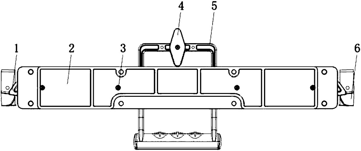
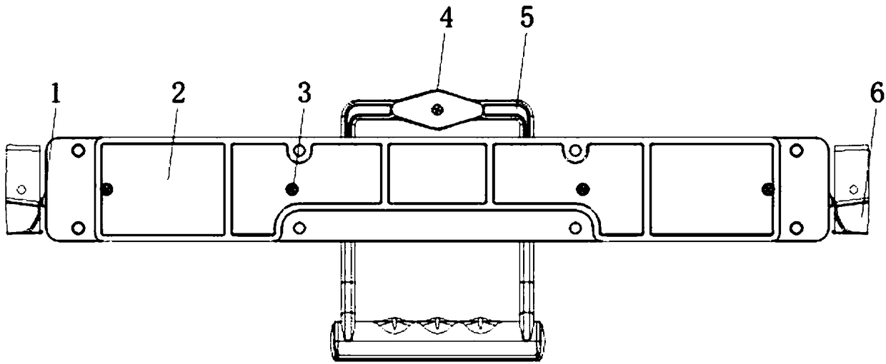
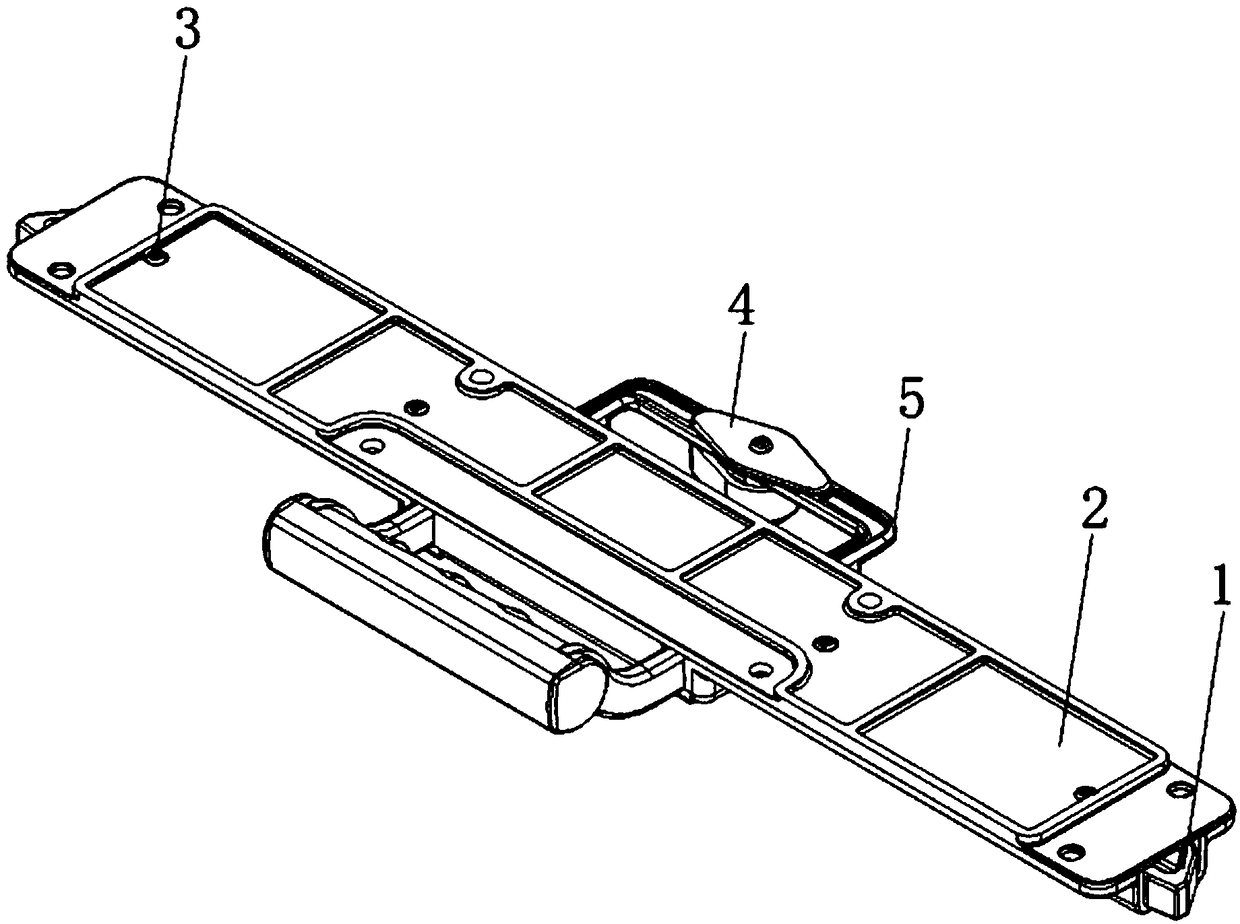
[0020] see Figure 1 to Figure 5 , an embodiment provided by the present invention: a zipper structure, including a lock strip 1, an upper lock cover 2, a handle 5 and a lower lock cover 7, the lower lock cover 7 is provided with a sliding groove 15, and the sliding groove 15 is provided with a limit Position post 16 and spring fixing block 17, limit groove 9 and spring groove 14 are provided on the lock bar 1, and two limit grooves 9 are all opened on each lo...


PUM


Abstract

The invention discloses a drawing and locking structure which comprises a lock bar, an upper lock cover, a handle and a lower lock cover. A sliding groove is formed in the lower lock cover, a limit column and a spring fixing block are arranged in the sliding groove, a limit groove and a spring groove are formed in the lock bar, the lock bar is mounted in the sliding groove of the lower lock coverthrough the limit groove, the limit column and a spring fixing block in a limited manner, the limit column, the spring fixing block and the lock bar form a spring base, a spring is arranged in the spring base, the handle is mounted in the inner middle of the lower lock cover, sealing covers are mounted at two ends of the handle, a rotating block is mounted on the surface of the bottom of one end of the handle, a limit part is movably mounted on the surface of one side of the handle backing the rotating block through a screw, the handle is mounted on the lock bar through a bearing groove and abearing in a limited manner, the upper lock cover is connected with the lower lock cover through a screw in a threaded manner, and the handle is connected with lock block through the lock bar in a limited and clamped manner. The drawing and locking structure has the advantage that a drawn panel can be limited and fixed.

Description

technical field [0001] The invention relates to the technical field of zippers, in particular to a zipper structure. Background technique [0002] Although the existing storage box has a pull-out structure, it can only limit and fix the drawer when pulling, and cannot limit and fix the drawable panel, which easily leads to the drawer being easily pulled out. It is very inconvenient to pull out the panel together. Contents of the invention [0003] The purpose of the present invention is to provide a zipper structure, which has the advantage of being able to limit and fix the pullable panel, and solves the problem that although the existing storage box is a pull-out structure, it can only limit the drawer when pulling. The position is fixed, and the drawable panel cannot be limited and fixed, which easily leads to the problem that the drawable panel is easily pulled out when the drawer is pulled out, which is very inconvenient. [0004] In order to achieve the above objec...

Claims


Application Information

Patent Timeline
Patent Type & Authority Applications(China)
IPC IPC(8): A47B88/477A47B88/90
CPCA47B88/477A47B88/90
Inventor 王冠文加里·雷蒙德·普兰特
Owner 王冠文
Why Eureka
Try Eureka