
A copper wire quick peeling recovery device

A recovery device, a fast technology, used in cable installation devices, cable installation, equipment for dismantling/armored cables, etc., can solve problems such as complicated operations, easy to pull and break copper wires, and inability to move the wire take-up device.

Active Publication Date: 2021-03-12
鹰潭瑞鑫铜业有限公司
View PDF16 Cites 0 Cited by
  • Summary
  • Abstract
  • Description
  • Claims
  • Application Information

AI Technical Summary

Problems solved by technology

[0003] In the prior art, the old copper wire peeling and packaging device has the disadvantages of large damage to the copper wire, complicated operation, and low work efficiency
More importantly, as the packaging progresses, the radius of the take-up shaft covered with copper wire gradually increases. Since the angular velocity of the take-up shaft is constant, the tension formula of the take-up It can be seen that the pulling force of the take-up will gradually increase, and the copper wire will be easily broken, resulting in the interruption of the packaging and recycling process; at the same time, during the take-up process, the take-up device cannot move, making the take-up efficiency low

Method used


Image

  • A copper wire quick peeling recovery device
  • A copper wire quick peeling recovery device

Examples


Embodiment Construction

[0015] An embodiment of the present invention will be further explained below in conjunction with the accompanying drawings.

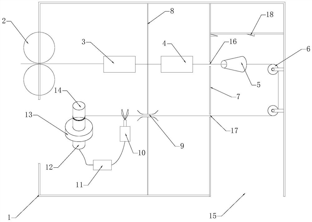
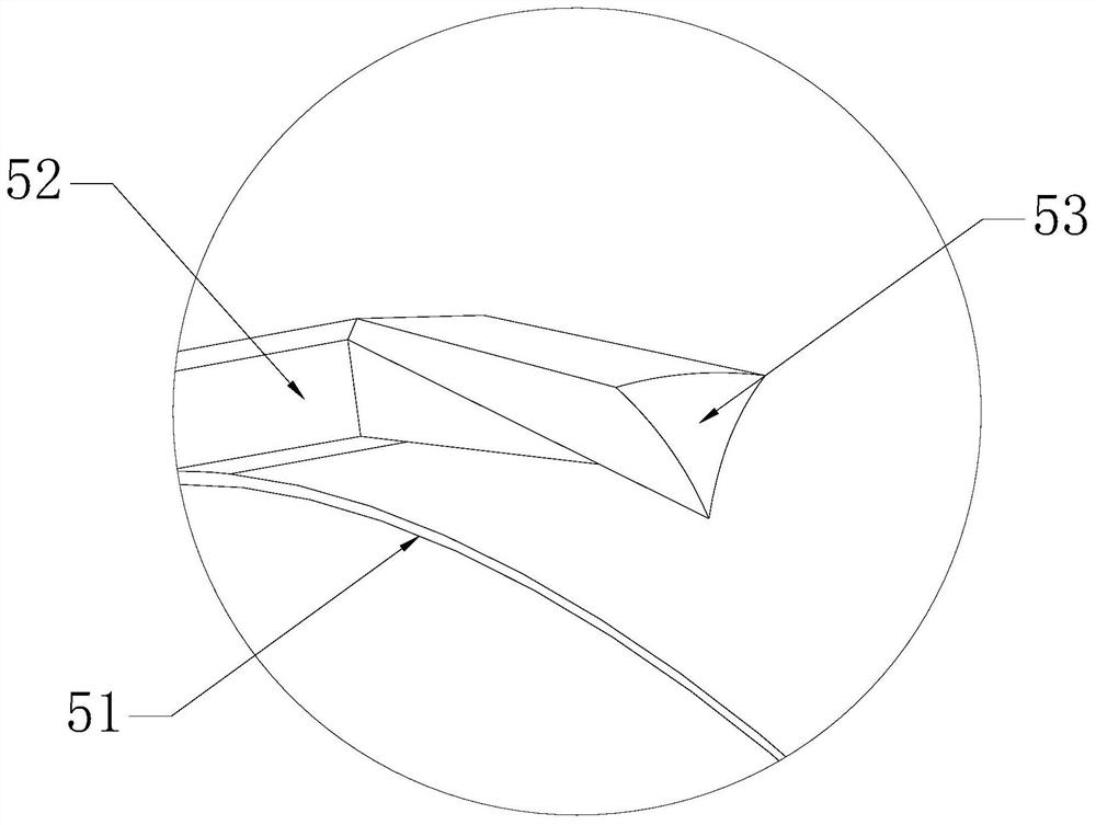
[0016] A copper wire rapid peeling recovery device, including a box body 1, an extrusion wheel 2, a heating box 3, a quenching box 4, a ring knife 5, a pulley 6, a barrier net 7, a sliding rod 8, a wire slider 9, and a pneumatic shear 10 , linkage controller 11, motor 12, torque protector 13 and take-up pulley 14.

[0017] Extrusion wheels 2 are arranged on the box body 1, and the gap between the extrusion wheels 2 is slightly smaller than the diameter of the recycled copper wire. The recovered copper wire is extruded from between the extrusion wheels 2 and becomes a straight line to enter the subsequent process.

[0018] A heating box 3 is arranged inside the box body 1, and the copper wire in a collimated state enters from one end of the heating box 3, and exits from the other end after being baked at a high temperature. Most of the recycled copper ...


PUM


Abstract

A rapid copper wire peeling and recycling device comprises a box body, an extrusion wheel, a heating box, a quenching box, a cutting ring, a pulley, a movable blade, a blocking net, a sliding rod, a wire sliding block, a pneumatic shear, a linkage controller, a motor, a torsion protector and a take-up wheel. The extrusion wheel is arranged at the left end of the box body, the heating box, the quenching box and the cutting ring are arranged in the box body, and the heating box is arranged at the right side of the extrusion wheel; the quenching box is arranged at the right side of the heating box, the cutting ring is arranged at the right side of the quenching box, and the blocking net is arranged in the box body and is located between the quenching box and the cutting ring; a first round through hole and a second round through hole are formed in the blocking net, the first round through hole directly faces the cutting ring, and the second round through hole directly faces the pulley; the pulley is arranged at the right end in the box body, the sliding rod is fixedly arranged in the box body, and the wire sliding block is movably arranged on the sliding rod; the pneumatic shear and the take-up wheel are arranged in the box body and are located at the left side of the second round through hole, the pneumatic shear is located at the right side of the take-up wheel, and the take-upwheel is connected with the motor through the torsion protector. The torsion protector is connected with the pneumatic shear through the linkage controller, the moving blade is arranged at the right side of the box body, and a leaking opening is formed at the bottom of the box body. According to the device, the insulating skin can be efficiently removed, the pulling force on the copper wire can belimited, the copper wire is prevented from being snapped, and the recovery is more efficient.

Description

technical field [0001] The invention relates to the field of copper wire recycling, in particular to a copper wire quick peeling and recycling device. Background technique [0002] Copper has good electrical conductivity, so it is widely used to make wires, but because copper is a precious and non-renewable resource, old copper wires are generally recycled. There is a very important step in recycling old copper wires, which is peeling Therefore, there is a peeling and packing device for old copper wire recycling. [0003] In the prior art, the old copper wire peeling and packaging device has the disadvantages of large damage to the copper wire, complicated operation, and low work efficiency. More importantly, as the packaging progresses, the radius of the take-up shaft covered with copper wire gradually increases. Since the angular velocity of the take-up shaft is constant, the tension formula of the take-up It can be seen that the pulling force of the take-up will gradua...

Claims


Application Information

Patent Timeline
Patent Type & Authority Patents(China)
IPC IPC(8): H02G1/12
CPCH02G1/1251H02G1/1275
Inventor 陈晓东
Owner 鹰潭瑞鑫铜业有限公司
Learn More