Belt locking mechanism, head supporting body installation structure, seat main body installation structure and shopping vehicle

A locking mechanism and technology with a lock, which is applied in the field of shopping carts, can solve the problems of complex structure, complicated assembly operations, and increased manufacturing costs, and achieve the effects of simple assembly, reduced manufacturing costs and maintenance costs, and simplified manufacturing operations

Active Publication Date: 2012-06-13
COMBI CORP
View PDF2 Cites 0 Cited by
  • Summary
  • Abstract
  • Description
  • Claims
  • Application Information

AI Technical Summary

Problems solved by technology

[0011] However, the belt lock mechanism 60 built into the guard 52 is as Figure 13 As shown, it is composed of a plurality of plates 61-63, brackets 64, 65, buttons 66, metal parts 67 supporting the buttons 66, link members 68, 69, etc., so the structure is complicated, and the assembly work is also complicated. Multiple parts are required, so the manufacturing cost is also increased

Method used


Image

  • Belt locking mechanism, head supporting body installation structure, seat main body installation structure and shopping vehicle
  • Belt locking mechanism, head supporting body installation structure, seat main body installation structure and shopping vehicle
  • Belt locking mechanism, head supporting body installation structure, seat main body installation structure and shopping vehicle

Examples


no. 1 Embodiment approach

[0075] Embodiments of the present invention will be described below with reference to the drawings.

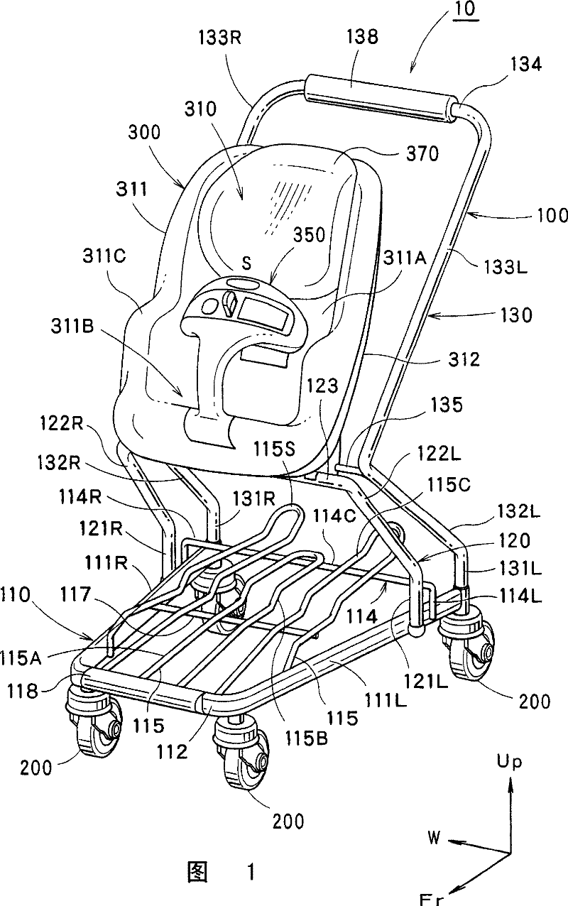
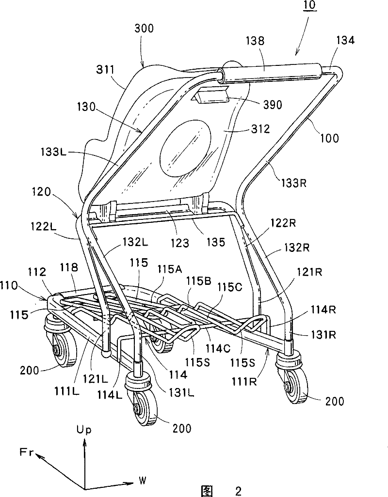
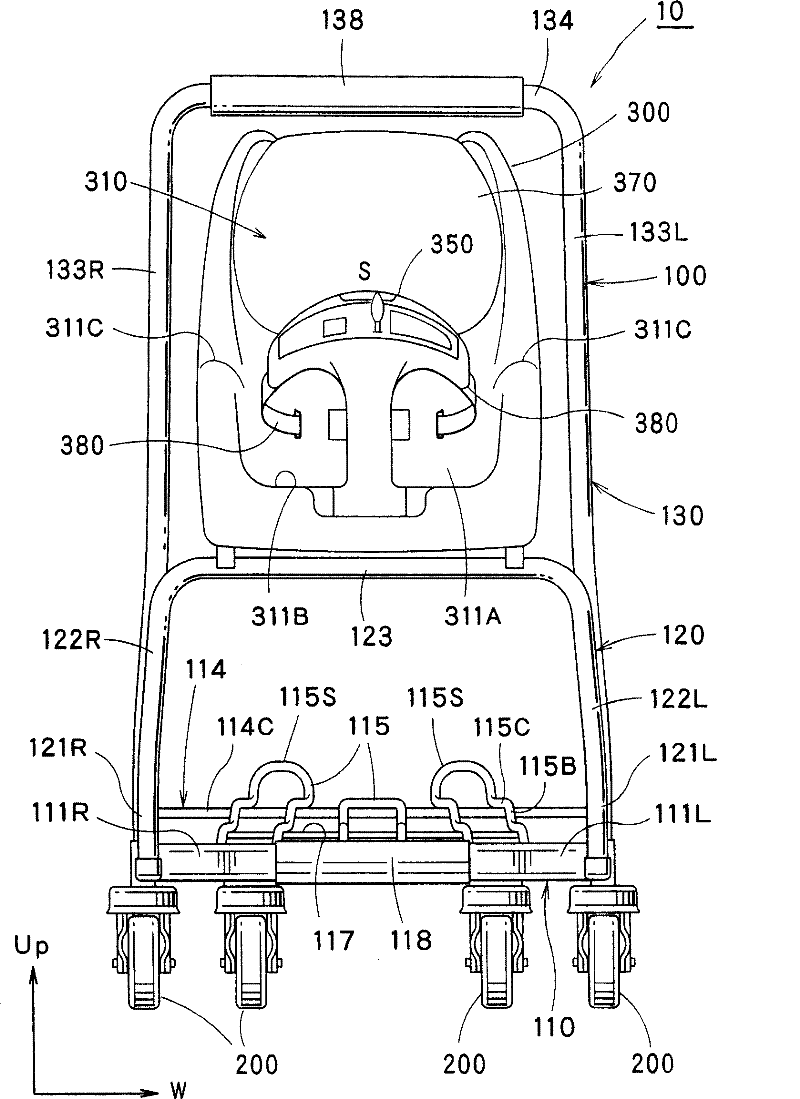
[0076] figure 1 It is a front perspective view of the shopping cart 10 according to the first embodiment of the present invention, figure 2 Yes figure 1 The rear perspective view of the shopping cart 10, image 3 Yes figure 1 The main view of the shopping cart 10, Figure 4 Yes figure 1Side view of a shopping cart 10. Fr in the figure represents the front of the shopping cart, Up represents the top, and W represents the width direction of the shopping cart. As shown in these figures, the shopping cart 10 includes a vehicle body 100 , traveling wheels 200 attached thereto, and a child seat 300 supported by the vehicle body 100 .

[0077] The main body 100 constituting the shopping cart 10 is constituted by a frame in which a plurality of steel pipes are bent and welded to each other. Specifically, the vehicle body 100 includes a base frame 110 , a seat support fram...

no. 2 Embodiment approach

[0141] Next, according to Figure 14 to Figure 18 A second embodiment of the present invention will be described.

[0142] The basic structure of the shopping cart 10 according to the first embodiment has been described above, but the shopping cart 10 according to this embodiment is characterized by the attachment structure of the head support 370 to the back portion 311A ​​of the seat main body 310 . It will be described in detail below.

[0143] In this embodiment, for Figure 1 to Figure 11 Components that are the same as those in the first embodiment shown are assigned the same reference numerals, and detailed description thereof will be omitted.

[0144] Figure 14 It is a perspective view which shows the seat main body 310 and the head support body 370 which show the feature of this invention. Figure 15 Yes Figure 14 An enlarged view of portion X of the seat body 310 is shown, Figure 16 Yes Figure 14 An enlarged view of the Y portion of the head support 370 is...

no. 3 Embodiment approach

[0158] Next, according to Figure 19 to Figure 29 A third embodiment of the present invention will be described.

[0159] In the first embodiment, the basic structure of the shopping cart 10 was described, but this embodiment is based on the support structure of the seat body 310 based on the support frame 140 formed by the cart body 100, and the seat body 310 can be rotated in stages. The aspect of the reclining adjustment mechanism which selectively adjusts the reclining angle is characteristic.

[0160] In this embodiment, for Figure 1 to Figure 11 Components that are the same as those in the first embodiment shown are assigned the same reference numerals, and detailed description thereof will be omitted.

[0161] Figure 19 It is a figure showing the attachment structure which attaches the seat main body 310 to the support frame 140 which consists of the vehicle main body 100, and the reclining adjustment mechanism which rotates the seat main body 310 and adjusts the r...


PUM


Abstract

A belt locking mechanism for locking the drawn action for a belt has a bottom plate (410), a rotary member (420) rotatably supported on the bottom plate, and an elastic member (430) for applying force to the rotary member. The bottom plate (410) has a narrow slot (411) for inserting the belt and fixed friction parts (412, 413) adjacent to the narrow slot. The rotary member (420) has a movable friction part (422A) and is bearing the force applied by the elastic member (430) thereby the movable friction part (422A) is pressed to the narrow slot and the fixed friction parts (412, 413). A belt 380 drawn from the back side of the bottom plate (410) through the narrow slot (411) is clamped and locked among the movable friction part (422A) and the fixed friction parts (412, 413). If the rotary member (420) is made to rotate by conquering the force of the elastic member (430), the movable friction part (422A) is made to move from the narrow slot (411) and the fixed friction parts (412, 413), then the lock of the belt (380) will be released.

Description

technical field [0001] The present invention relates to a belt lock mechanism for locking a seat belt for a child seat, a head support mounting structure, a seat main body mounting structure, and a shopping cart. Background technique [0002] In store facilities such as supermarkets and large-scale retail stores in recent years, shopping carts are prepared to transport the products purchased by shoppers, and shoppers move around the store facilities while pushing the shopping carts, and put the products in the shopping cart. Shopping in the basket. In this way, since a plurality of products can be stacked in the shopping cart, the shopper can carry out shopping more easily than in the case of moving while holding the shopping basket. [0003] Furthermore, recently, as shown in Patent Document 1, shopping carts equipped with child seats are also spreading. In addition, since the shopping cart is moved while the child is seated in the child seat, in order to prevent the chil...

Claims


Application Information

Patent Timeline
Patent Type & Authority Patents(China)
IPC IPC(8): B62B5/00B62B3/14B62B5/08
Inventor 依田洋光大知早惠
Owner COMBI CORP
Why Eureka
Try Eureka