
Cloud-mist type air-purifying device

An air purification device, cloud and mist technology, applied in the field of air purification, can solve the problems of low speed of dust-laden airflow, large structure size, complex device, etc., and achieve the effect of less water consumption, compact structure and reasonable design

Active Publication Date: 2018-09-28
JIANGSU UNIV
View PDF8 Cites 3 Cited by
  • Summary
  • Abstract
  • Description
  • Claims
  • Application Information

AI Technical Summary

Problems solved by technology

Patent CN201610803531 "A tail gas treatment device and treatment method" adopts an ultrasonic atomization nozzle to make the droplet particle size about 20 microns, and uses sound wave reunion to strengthen the collision reunion rate of liquid droplets and fine particles. Due to the high energy consumption of sound wave reunion, The mechanism of action is not clear enough, and there is still a distance from practical application
Chinese patent CN201520441267 "Cloud-type dust removal system" is equipped with a liquid mist generator, a particle growth area and a cloud-type dust removal device. The dust-laden airflow and liquid mist mix slowly, and the speed of the dust-laden airflow is relatively small. The whole set of devices is relatively complicated and has a large structural size. Its promotion and application are limited

Method used


Image

  • Cloud-mist type air-purifying device
  • Cloud-mist type air-purifying device
  • Cloud-mist type air-purifying device

Examples


Embodiment Construction

[0025] The present invention will be further described below in conjunction with the accompanying drawings and specific embodiments, but the protection scope of the present invention is not limited thereto.

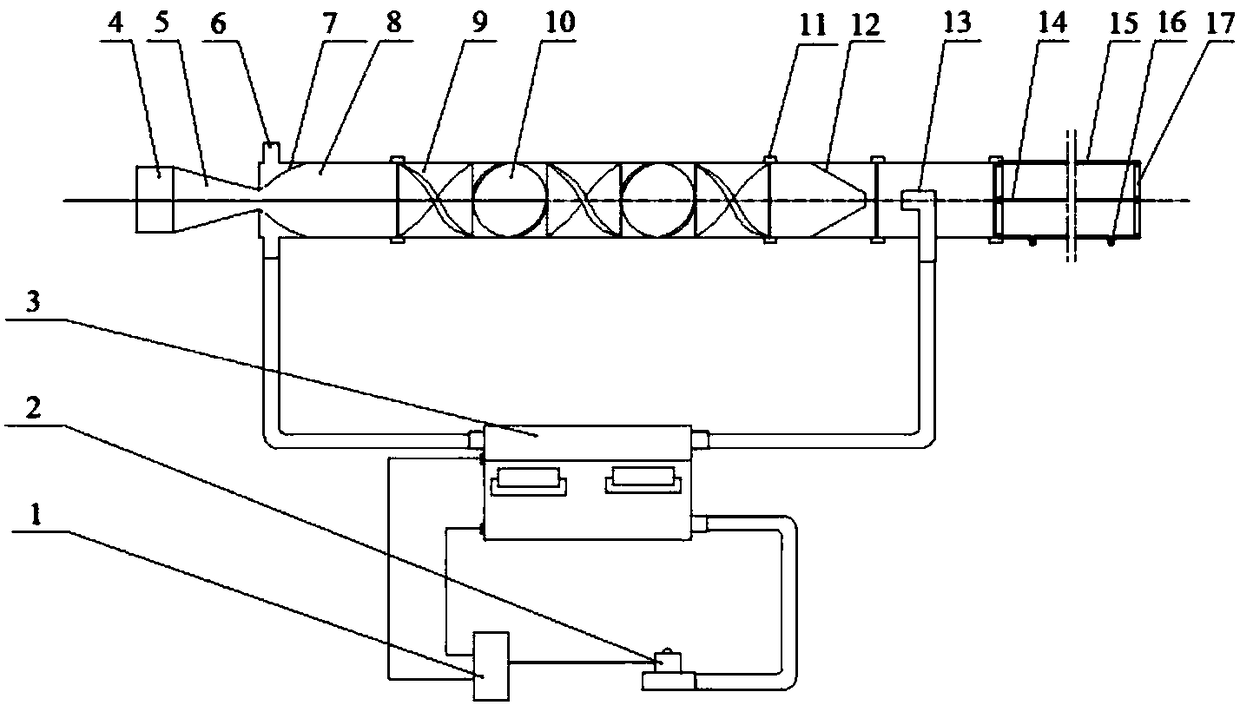
[0026] Such as figure 1 As shown, a cloud-type air purification device according to the present invention includes a water tank 3 for holding water, a fan 4, a tapered section 5, a cloud primary mixing section 8, a secondary mixing section, a spray section, and a tertiary mixing section. Section, deposition section, cloud mist suction pipe 13, cloud mist generator 19, liquid level controller 1, electromagnetic valve 2, the low liquid level sensor 18 that is used to measure the low water level in the water tank 3, is used to measure the high water level in the water tank 3 High level sensor 20.

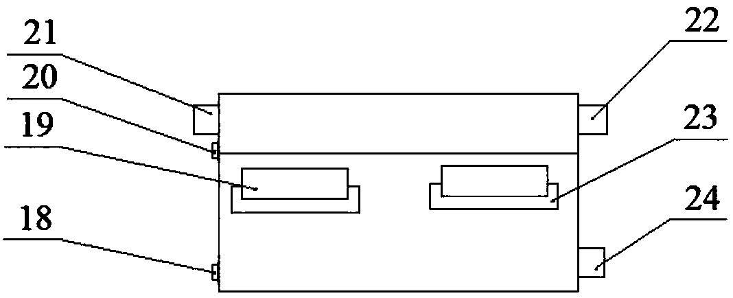
[0027] Such as figure 2 As shown, the cloud generator 19 is pasted on the buoy 23, and the buoy 23 is suspended in the water of the water tank 3, and the cloud generator 19 is ...


PUM


Abstract

The invention provides a cloud-mist type air-purifying device. The device comprises a water tank used for accommodating water, a draught fan, cloud-mist generators, and a gradually-contractile section, a cloud-mist primary mixing section of which the side wall is provided with a plurality of cloud-mist inlets, a secondary mixing section of which the interior is provided with partition sheet groups, an injection section of which the interior is provided with a rotary jet flow spray nozzle, a tertiary mixing section of which the interior is provided with a cloud-mist suction pipe and a deposition section which communicate with one another in sequence; and the interior of the deposition section is provided with a rod type electrode and a TiO2 coating, the bottom of the deposition section is provided with water collecting openings, and the tail end of the deposition section is provided with an opening. According to the device provided by the invention, a principle of flowing of a fluid isutilized to design each mixing section, the flow characteristics of a wall-attached jet flow and a rotating jet flow are comprehensively used, so that automatic suction of cloud and mist is realized,full action of collision, coagulation and agglomeration processes of fine particulate matter in an airflow and small liquid droplets of the cloud and mist is guaranteed, formation of larger-sized liquid droplets containing particulate matter is promoted, and the larger-sized liquid droplets are deposited and recovered under the action of electrostatic force; and the device has high removing efficiency of PM2.5, low energy consumption, low water consumption and a compact structure, and is convenient for transformation of a current ventilation system.

Description

technical field [0001] The invention relates to the field of air purification, in particular to a cloud-type air purification device. Background technique [0002] In recent years, haze weather has occurred in the market. Fine particulate matter PM2.5 has been suspended in the air for a long time, and has a large specific surface area, which is easy to adsorb and gather viruses and bacteria. After PM2.5 enters the alveoli of the human body, it is easy to form deposits and cause respiratory diseases. Conventional dust removal equipment can effectively capture particles with a particle size greater than 10 microns, but it is often powerless to fine particles with a particle size of 0.1 to 2.5 microns. [0003] To solve this problem, most air purification devices use fine water mist to increase the capture rate of fine particles. However, simply using fine water mist to adsorb and capture fine particles, still a considerable part of the fine particles escape, and the water co...

Claims


Application Information

Patent Timeline
Patent Type & Authority Applications(China)
IPC IPC(8): B01D50/00B03C3/017
CPCB01D50/00B03C3/017
Inventor 王晓英王军锋霍元平王贞涛王东保武识博陆启明
Owner JIANGSU UNIV
Learn More