a brake pedal

A brake pedal and pedal technology, applied in the field of brake pedals, can solve the problems of affecting reaction time, muscle fatigue of the right foot, and inability to apply the brake pedal, so as to achieve the effect of automatic adjustment and satisfying driving safety.

Active Publication Date: 2020-04-10
ZHUJI TIANYA TECH CO LTD
View PDF5 Cites 0 Cited by
  • Summary
  • Abstract
  • Description
  • Claims
  • Application Information

AI Technical Summary

Problems solved by technology

And different drivers' stature and foot size are all different, so the bottom of the right foot of different drivers can't fit well with the brake pedal in the process of stepping on the brake pedal, so that the operator steps on the brake. The process is not smooth
Especially when driving for a long time, the uneven braking process with the right foot will not only affect the reaction time in case of sudden braking, but also easily lead to muscle fatigue and even cramps in the right foot, which will affect driving safety
[0003] It is also worth mentioning that the industry has also considered the flexible connection between the brake pedal and the brake pedal rod, that is, the brake pedal can be swung within a small angle range, but the brake pedal that can swing arbitrarily during normal driving is safe. risk, and in the field of auto parts, the safety performance of brake components is the primary consideration, so this type of brake pedal that is active during driving cannot be used in the automotive field

Method used


Image

  • a brake pedal
  • a brake pedal
  • a brake pedal

Examples


Embodiment 1

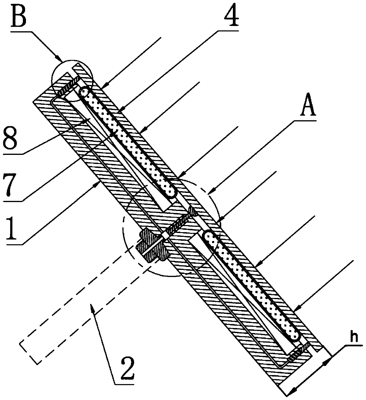
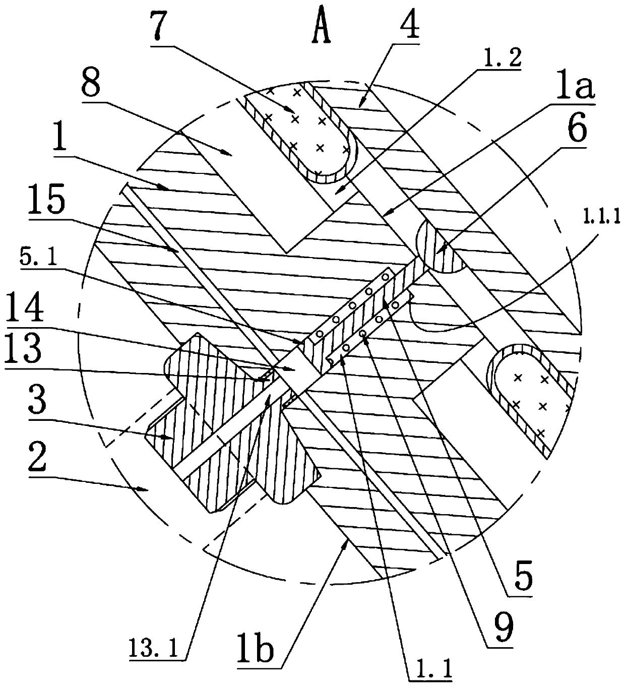
[0028] The present invention provides a kind of brake pedal, it comprises such as figure 1 and figure 2 As shown in the pedal body 1, the back side 1b of the pedal body 1 is provided with a connecting portion 3 connected to the brake pedal lever 2. The connecting portion 3 is a connecting joint, and the connecting portion 3 is connected to the brake pedal lever 2 on the car to complete The installation of the brake pedal can be threaded, welded, clamped, etc. The front 1a of the pedal body 1 is covered with a cover plate 4, and a connecting rod 5 is arranged between the cover plate 4 and the pedal body 1. The connecting rod The upper end of 5 is connected to the central position of cover plate 4 through universal joint 6, and said universal joint 6 may be a fish-eye joint, and said pedal body 1 is provided with a mounting hole 1.1 at a position corresponding to connecting rod 5 , the connecting rod 5 is slidingly fitted with the mounting hole 1.1 along the thickness directio...

Embodiment 2

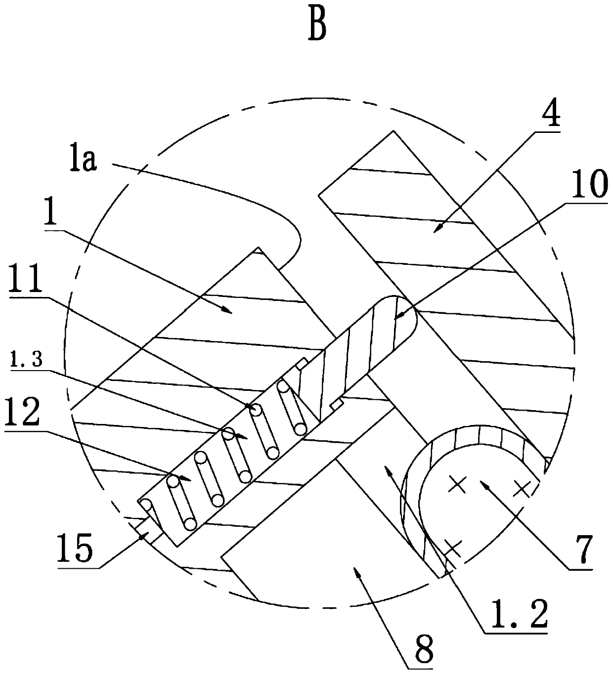
[0034] Between the front face 1a of the pedal body 1 and the lower end surface of the cover plate 4, a plurality of jack posts 10 are arranged, and the pedal body 1 is provided with guide holes 1.3 which are slidably fitted with each jack post 10, and the guide holes 1.3 are along the pedal body 1. The thickness direction h of the guide hole 1.3 is provided with a thrust spring 11, the lower end of the thrust spring 11 abuts against the inner surface of the guide hole 1.3, and the upper end of the thrust spring 11 abuts against the lower end surface of the top post 10, the said The thrust spring 11 drives the push post 10 to move upward along the axial direction of the guide hole 1.3 under the action of its own elastic force until the upper end of the push post 10 abuts against the lower end surface of the cover plate 4 . Such as image 3 As shown, the upper end of the top post 10 is arc-shaped, and the lower end of the top post 10 is provided with a limit bump for limiting th...

Embodiment 3

[0039] There are multiple mounting grooves 1.2, and multiple mounting grooves 1.2 are arranged at intervals along the circumferential direction of the axis of the connecting rod 5. Each mounting groove 1.2 is respectively provided with a magnetorheological elastomer 7, and the pedal body 1 is located in each magnetorheological elastic body. The position corresponding to the body 7 is provided with an excitation device 8 .


PUM


Abstract

The invention discloses a brake pedal, comprising a pedal body. A connecting part is arranged on the back face of the pedal body, and the front of the pedal body is covered with a cover board. A connecting rod is arranged between the cover board and the pedal body, and the upper end of the connecting rod and the center position of the cover board are connected through a universal joint. Mounting holes are formed in the pedal body, a flange is arranged at the lower end of the connecting rod, and the mounting holes are internally provided with stepped faces abutting against the flange. The frontof the pedal body is recessed to form mounting grooves, magnetorheological elastomers are arranged in the mounting grooves, excitation devices are arranged in the pedal body, and the excitation devices are electrically connected with a vehicle power supply. The magnetorheological elastomers respond to the solidification of the magnetic field of the excitation devices or are restored to an elasticstate with the disappearance of the magnetic field. According to the brake pedal, the angle of the brake pedal can be automatically adjusted according to different drivers, and the brake pedal is fixed to a brake pedal rod in normal driving conditions

Description

technical field [0001] The invention relates to the technical field of components of an automobile brake system, in particular to a brake pedal. Background technique [0002] In the related art, the brake pedal is generally fixedly connected with the brake pedal rod, so the installation position of the brake pedal is fixed. And different drivers' stature and foot size are all different, so the bottom of the right foot of different drivers can't fit well with the brake pedal in the process of stepping on the brake pedal, so that the operator steps on the brake. The process is not smooth. Especially when driving for a long time, the uneven braking process of the right foot will not only affect the reaction time in case of sudden braking, but also easily lead to muscle fatigue and even cramps in the right foot, thus affecting driving safety. [0003] It is also worth mentioning that the industry has also considered the flexible connection between the brake pedal and the brake...

Claims


Application Information

Patent Timeline
Patent Type & Authority Patents(China)
IPC IPC(8): B60T7/06
CPCB60T7/06
Inventor 韩赛
Owner ZHUJI TIANYA TECH CO LTD
Why Eureka
Try Eureka