
Display device

A display device and display module technology, applied in nonlinear optics, instruments, optics, etc., can solve problems such as poor cutting, low processing efficiency of special-shaped cutting design, and limitation of screen ratio of display screens.

Active Publication Date: 2018-09-28
BOE TECH GRP CO LTD +1
View PDF3 Cites 98 Cited by
  • Summary
  • Abstract
  • Description
  • Claims
  • Application Information

AI Technical Summary

Problems solved by technology

Usually, the cameras of the camera module are set outside the display area of ​​the display screen, so that the screen-to-body ratio of the display screen is limited.
At present, in order to increase the screen-to-body ratio of the display screen, some manufacturers have cut the display screen to form a special-shaped display screen, but the processing efficiency of the special-shaped cutting design is low, and it is easy to cause poor cutting

Method used


Image

  • Display device
  • Display device
  • Display device

Examples


Embodiment Construction

[0028] Specific embodiments of the present invention will be described in detail below in conjunction with the accompanying drawings. It should be understood that the specific embodiments described here are only used to illustrate and explain the present invention, and are not intended to limit the present invention.

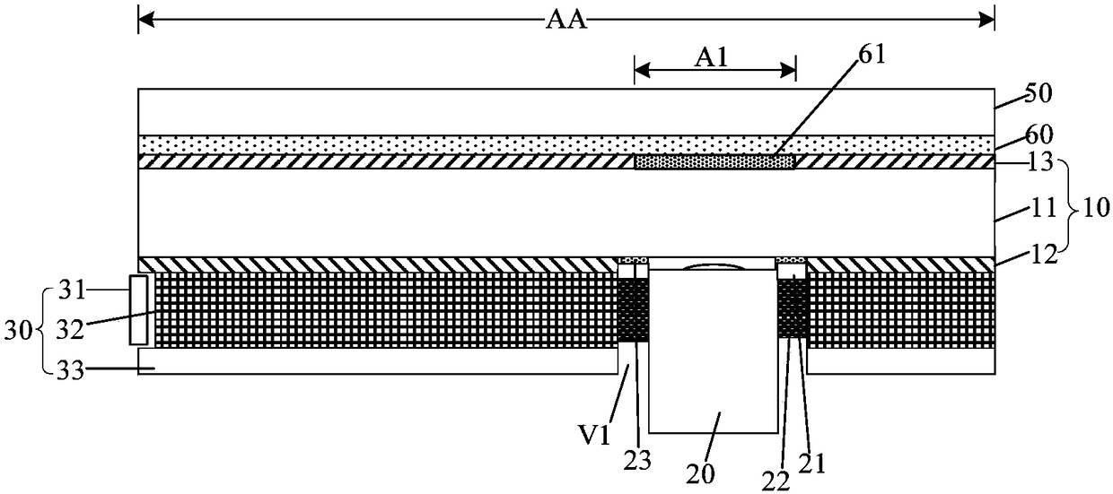
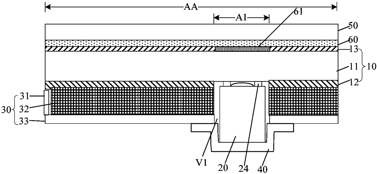
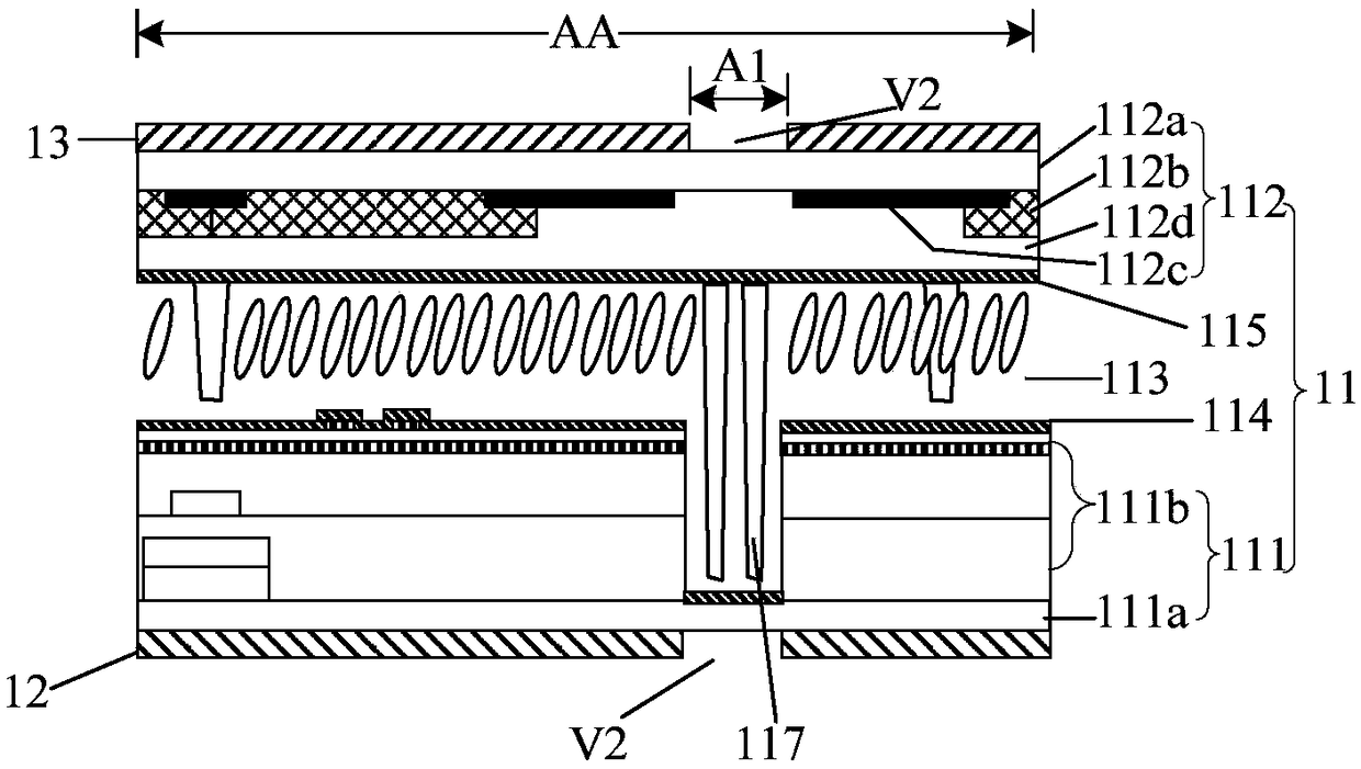
[0029] In order to increase the screen-to-body ratio of a display device while ensuring production efficiency and product yield, the present invention provides a display device, figure 1 is the first structural schematic diagram of the display device, figure 2 It is a schematic diagram of the second structure of the display device. Such as figure 1 and figure 2 As shown, the display device includes a display module 10 and a camera 20. The camera 20 is located in the display area AA of the display module 10, and is located on the side of the display module 10 away from its light emitting direction. Wherein, the display area AA includes a light incident area...


PUM


Abstract

The invention provides a display device. The display device comprises a display module and a camera located in a display area of the display module and located on one side, backing to the light emergent direction, of the display module; the display area of the display module comprises a light incidence area corresponding to a lens of the camera, and the light incidence area allows outside light topenetrate through, so that the penetrating outside light is irradiated to the lens of the camera. The screen-to-body ratio of the display device can be increased under the condition that the production efficiency and the product yield are guaranteed.

Description

technical field [0001] The present invention relates to the field of display technology, in particular to a display device. Background technique [0002] With the continuous development of science and technology, artificial intelligence (AI) has become a future development trend, and camera modules are one of the important structures for realizing artificial intelligence, so display devices such as notebooks and mobile phones will integrate camera modules. Usually, the cameras of the camera module are arranged outside the display area of ​​the display screen, so that the screen-to-body ratio of the display screen is limited. At present, in order to increase the screen-to-body ratio of the display screen, some manufacturers have cut the display screen to form a special-shaped display screen, but the processing efficiency of the special-shaped cutting design is low, and it is easy to cause poor cutting. Contents of the invention [0003] The present invention aims to solve ...

Claims


Application Information

Patent Timeline
Patent Type & Authority Applications(China)
IPC IPC(8): G02F1/13357G02F1/1335
CPCG02F1/133528G02F1/133615G02F1/13318G02F1/133371
Inventor 李金鹏翟明李沛李丹曹鹏军舒宗英姜永强王志远陈智勇陈寅伟李响王光泉孙海威董恩凯
Owner BOE TECH GRP CO LTD
Learn More