Dust collector and operation method thereof

An operation method and technology of vacuum cleaners, which are applied in the directions of vacuum cleaners, suction filters, cleaning equipment, etc., can solve the problems of laborious operation and inconvenient use when the vacuum cleaner pours dust

Pending Publication Date: 2018-10-09
SKYBEST ELECTRIC APPLIANCE SUZHOU CO LTD
View PDF0 Cites 7 Cited by
  • Summary
  • Abstract
  • Description
  • Claims
  • Application Information

AI Technical Summary

Problems solved by technology

[0004] The purpose of the present invention is to provide a vacuum cleaner and its operating method to solve the technical

Method used


Image

  • Dust collector and operation method thereof
  • Dust collector and operation method thereof
  • Dust collector and operation method thereof

Examples


Embodiment 1

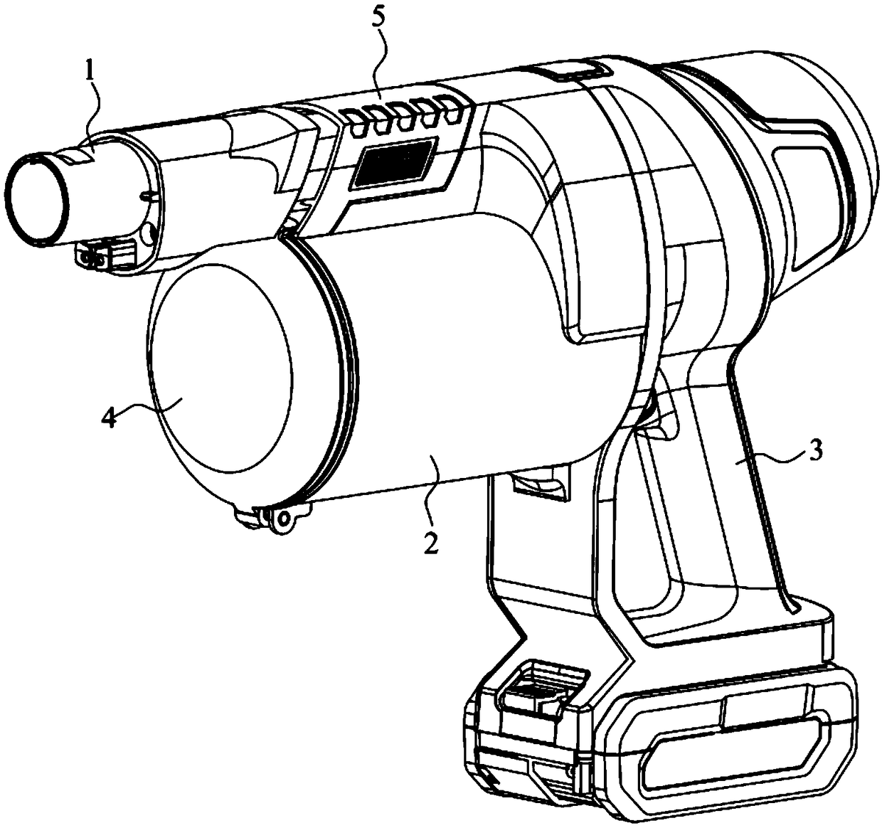
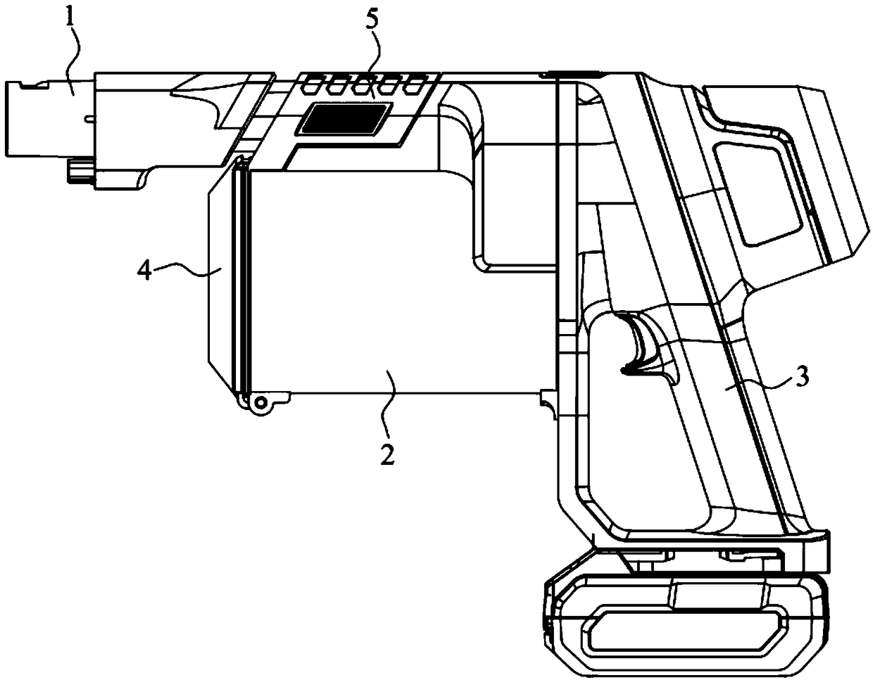
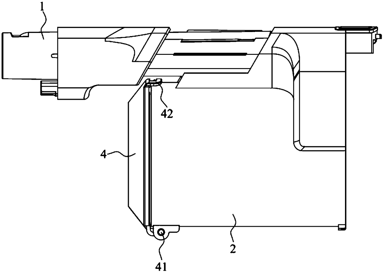
[0036] see Figure 1 to Figure 4 , the embodiment of the present invention provides a vacuum cleaner, including an air intake pipe 1, a dust cup 2, a handle 3 and a cup cover 4, the dust cup 2 is located on the lower side of the air intake pipe 1, and one end is connected to the handle 3, and the dust cup 2 is far away from the handle 3 One end of the container is provided with an ash outlet 21, and the ash outlet 21 is provided with a cup cover 4, and the cup cover 4 can open or close the ash outlet 21.

[0037] One end of the cup cover 4 close to the intake pipe 1 is clamped with the dust cup 2, and the other end of the cup cover 4 is hinged with the dust cup 2; Sliding in the direction of the axis to push the cup cover 4 and the dust cup 2 out of engagement. The clamping method of the cup cover 4 and the dust cup 2 can be a lock, a clip or a buckle assembly. During the sliding process, the slider 5 unlocks the clip joint between the cup cover 4 and the dust cup 2, so that ...

Embodiment 2

[0049] Figure 15 Embodiment 2 is shown, in which components identical or corresponding to those in Embodiment 1 are identified with reference numerals corresponding to Embodiment 1. For simplicity, only the differences between Embodiment 2 and Embodiment 1 are described. The difference is that an operating part 54 is provided on at least one side of the main body part 52 , and when the sliding part 5 is pushed by hand, the hand contacts the operating part 54 , which is convenient for pushing the sliding part 5 smoothly.

[0050] In this embodiment, the operating part 54 is disposed at an end of the friction part 53 close to the cup cover 4 . When pushing the sliding part 5 by hand, under the cooperation of the friction part 53 and the operating part 54, the hand is limited, so that the hand is in close contact with the sliding part 5, which is convenient for pushing the sliding part 5 smoothly.

[0051] The embodiment of the present invention also provides a method for oper...


PUM


Abstract

The invention discloses a dust collector and an operation method thereof. The dust collector comprises an air feeding pipe and a dust cup, wherein a cup cover is arranged on the dust cup; one end of the cup cover is hinged with the dust cup, and the other end of the dust cup is clamped with the dust cup; a sliding piece is arranged on the air feeding pipe in a sleeving manner; the sliding piece isconfigured to slide in the axial direction of the air feeding pipe to push the cup cover to be separated from or clamped with the dust cup. The operation method of the dust collector comprises pushing the sliding piece in the axial direction of the air feeding pipe to drive the cup cover to be separated from or clamped with the dust cup. The dust collector achieves an effect of pouring out ash through one key, and the operation saves effort and is convenient; the sliding piece is arranged on the air feeding pipe in a sleeving manner, so that dust cannot fall onto hands when the sliding pieceis pushed. Therefore, a pollution source gets far away from a user, and the dust collector is sanitary and clean.

Description

technical field [0001] The invention relates to the technical field of cleaning equipment, in particular to a vacuum cleaner and an operating method thereof. Background technique [0002] The working principle of the vacuum cleaner is that the motor rotates at a high speed, and the air flow is sucked in from the suction port, and the air flow drives the dust into the dust bucket. The dust in the dust bucket needs to be cleaned frequently. [0003] Existing dust bucket generally all is to open the switch button of dust cup bottom cover by hand, and the dust cup bottom cover of dust bucket comes off automatically, and the dust in the dust bucket is poured out. There is a sealing ring at the bottom of the dust bucket. If the sealing ring is too loose, it will cause air leakage, which will reduce the suction of the vacuum cleaner; When pouring dust, because the bottom cover of the dust cup is not easy to fall off, the user needs to dig out the bottom cover of the dust cup by h...

Claims


Application Information

Patent Timeline
IPC IPC(8): A47L5/24A47L9/16A47L9/00
CPCA47L5/24A47L9/00A47L9/1683
Inventor 郁唯一白皙琳施金鑫
Owner SKYBEST ELECTRIC APPLIANCE SUZHOU CO LTD
Why Eureka
Try Eureka