Air conditioner upper cover fixing structure

A fixed structure, air conditioner technology, applied in the directions of heating and ventilation hoods/covers, etc., can solve problems such as deformation, and achieve the effect of preventing gaps and saving labor and convenient operation.

Inactive Publication Date: 2003-12-03
LG ELECTRONICS (TIANJIN) APPLIANCES CO LTD
View PDF0 Cites 5 Cited by
  • Summary
  • Abstract
  • Description
  • Claims
  • Application Information

AI Technical Summary

Problems solved by technology

[0002] Known air conditioner upper cover fixed structure such as figure 1 As shown, insert the L-shaped vertically protruding plug 12 at the bottom of both sides of the upper cover 10 into the connection hole 24 formed in the curved portion 22 of the upper end of the chassis 20, and then insert the upper cover 10 to the rear. There is a first connection hole 26 on the rear side, and the second connection hole 14 corresponding to it protrudes to form a screw hole 16 on the upper cover 10. There are T-shaped protrusions and fixed ends 18 on the upper cover 10. When the rear is inserted, the fixed end 18 is attached to the rear surface 20a of the casing 20, and the screw 30 is inserted into the first connecting hole 26 and the second connecting hole 14 from the rear side of the above-mentioned casing 20 to fix the upper cover 10 on the top of the casing 20, as is known on air conditioners. The problems in the cover fixing structure are as follows: during the connection process when the connecting plug 12 is inserted into the connecting hole 24, the upper cover 10 or the chassis 20 will be seriously deformed due to external force, and in addition, because the upper cover 10 and the chassis 20 do not coordinate with the upper cover 10 and the chassis. There is a gap between 20

Method used


Image

  • Air conditioner upper cover fixing structure
  • Air conditioner upper cover fixing structure
  • Air conditioner upper cover fixing structure

Examples


Embodiment Construction

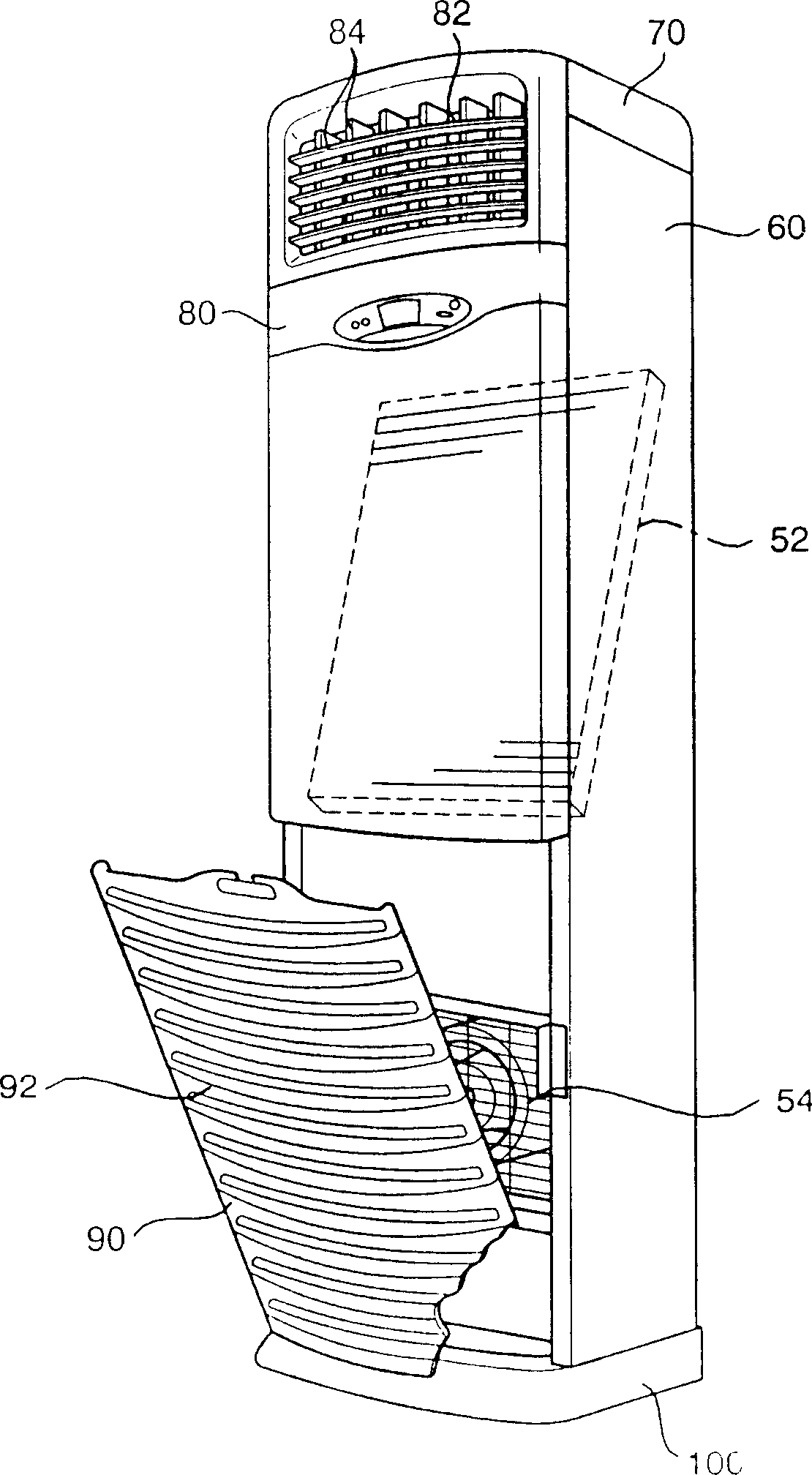
[0016] In order to further understand the content, characteristics and effects of the present invention and give examples of the following embodiments, the air conditioner of the present embodiment is as follows: figure 2 As shown, a heat exchanger 52 and an air blower 54 are provided on the front and the open interior of the cabinet 60, the upper end of the cabinet 60 is combined with the upper cover 70, and an air exhaust port 82 is arranged on the front of the upper cover 70 and the upper part of the cabinet 60. The air outlet 82 is equipped with the front upper panel 80 of the wind direction adjustment mechanism 84, and the lower front of the cabinet 60 is provided with a suction louver 90 for sucking in the air inlet 92 of indoor air, and the bottom of the cabinet 60 is provided with a support cabinet 60 and a foil suction louver 90 base 100 etc. to constitute the air conditioner.

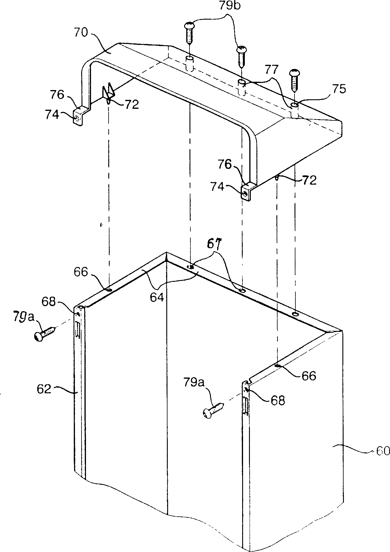
[0017] The above chassis 60 such as image 3 As shown, the front sides of the cabinet 60...


PUM


Abstract

A top cover fixing structure of air conditioner features that said top cover has the locating pins, the casing of air conditioner has holes matched with said locating pins to prevent top cover from moving, and the front and back edges of said top cover and casing are fixed to each other by screws. Its advantages are easy installing and no deformation.

Description

technical field [0001] The invention belongs to the field of air conditioning, in particular to an air conditioner upper cover fixing structure. Background technique [0002] Known air conditioner upper cover fixed structure such as figure 1 As shown, insert the L-shaped vertically protruding plug 12 at the bottom of both sides of the upper cover 10 into the connection hole 24 formed in the curved portion 22 of the upper end of the chassis 20, and then insert the upper cover 10 to the rear. There is a first connection hole 26 on the rear side, and the second connection hole 14 corresponding to it protrudes to form a screw hole 16 on the upper cover 10. There are T-shaped protrusions and fixed ends 18 on the upper cover 10. When the rear is inserted, the fixed end 18 is attached to the rear surface 20a of the casing 20, and the screw 30 is inserted into the first connecting hole 26 and the second connecting hole 14 from the rear side of the above-men...

Claims


Application Information

Patent Timeline
Patent Type & Authority Applications(China)
IPC IPC(8): F24F13/20
Inventor 金江永
Owner LG ELECTRONICS (TIANJIN) APPLIANCES CO LTD
Why Eureka
Try Eureka