
Transmission shaft fixing device

A technology for fixing devices and drive shafts, applied in the field of drive shafts, can solve problems such as inconvenient disassembly and scratches on the optical axis, and achieve the effect of easy disassembly

Inactive Publication Date: 2018-10-09
HENAN XINZHOU TRANSMISSION MACHINERY CO LTD
View PDF3 Cites 1 Cited by
  • Summary
  • Abstract
  • Description
  • Claims
  • Application Information

AI Technical Summary

Problems solved by technology

[0002] There are many devices for fixing the transmission shaft in the prior art, such as flat vise, three-jaw chuck, V-shaped block and other devices, but the above-mentioned fixing devices are easy to cause scratches on the surface of the optical shaft, and there are some other fixing devices. However, there is also the problem of inconvenient disassembly after fixing; therefore, in order to solve the above problems, a drive shaft fixing device is needed

Method used


Image

  • Transmission shaft fixing device
  • Transmission shaft fixing device

Examples


Embodiment Construction

[0012] The present invention will be further described below in conjunction with the accompanying drawings.

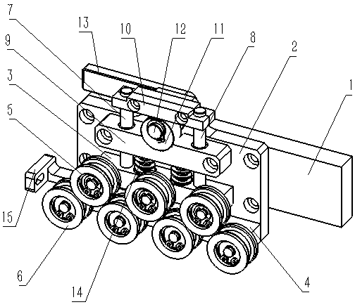
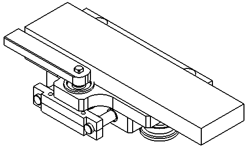
[0013] Such as figure 1 , figure 2 As shown, a drive shaft fixing device includes a vertical plate 1, the front end of the vertical plate 1 is provided with a mounting plate 2, the front of the mounting plate 2 is provided with a movable plate 3, and the lower part of the movable plate 3 is provided with a fixed plate 4 , the movable plate 3 is provided with a pressure wheel 5, the fixed plate 4 is provided with a supporting wheel 6 having the same structure as the pressure wheel 5, and the upper end of the movable plate 3 is symmetrically provided with a first guide shaft 7 and a second Two guide shafts 8, the first guide shaft 7 and the second guide shaft 8 are sleeved with a connecting plate 9, the upper end is provided with a limiting plate 10, and an eccentric wheel 11 is arranged between the connecting plate 9 and the limiting plate 10 , the eccentric wheel 11...


PUM


Abstract

The invention discloses a transmission shaft fixing device which comprises a stand plate. A mounting plate is arranged at the front end of the stand plate, and a movable plate is arranged in front ofthe mounting plate. A fixed plate is arranged below the movable plate, and a pressing wheel is arranged on the movable plate. Supporting wheels with the structures the same as that of the pressing wheel are arranged on the fixed plate. A first guide shaft and a second guide shaft are symmetrically arranged at the upper end of the movable plate and sleeved with a connecting plate. A limiting plateis arranged at the upper end of the first guide shaft and the upper end of the second guide shaft, and an eccentric wheel is arranged between the connecting plate and the limiting plate. The eccentricwheel is sleeved with a mounting shaft, and a pressing handle is arranged at the rear end of the mounting shaft. Springs are arranged between the movable plate and the connecting plate, and a guide block is arranged at the left end of the stand plate. Totally, the transmission shaft fixing device has the beneficial effects of being convenient to demount and free of scratching a transmission shaft.

Description

technical field [0001] The invention relates to the technical field of transmission shafts, in particular to a transmission shaft fixing device. Background technique [0002] There are many devices for fixing the transmission shaft in the prior art, such as flat vise, three-jaw chuck, V-shaped block and other devices, but the above-mentioned fixing devices are easy to cause scratches on the surface of the optical shaft, and there are some other fixing devices. However, there is also the problem of inconvenient disassembly after fixing; therefore, in order to solve the above problems, a transmission shaft fixing device is needed. Contents of the invention [0003] The main purpose of the present invention is to provide a transmission shaft fixing device that is easy to disassemble and does not cause scratches to the transmission shaft. [0004] In order to achieve the above object, the present invention provides a drive shaft fixing device, which includes a vertical plate,...

Claims


Application Information

Patent Timeline
IPC IPC(8): B25B11/00
CPCB25B11/00
Inventor 尚梦鸽尚亚民
Owner HENAN XINZHOU TRANSMISSION MACHINERY CO LTD
Learn More