Rail transit steel rail crack detection device

A technology of rail transit and flaw detection device, which is applied in transportation and packaging, railway car body parts, railway vehicle shape measuring instrument, etc., can solve problems such as inconvenience for operators to monitor in real time, prone to detection blind spots, and inability to adjust push rods, etc. It is easy to monitor and observe in real time, the adjustment process is simple and convenient, time-saving and labor-saving, and the adjustment process is time-saving and labor-saving.

Active Publication Date: 2018-10-09
盐城海诺斯自动化设备有限公司
View PDF6 Cites 8 Cited by
  • Summary
  • Abstract
  • Description
  • Claims
  • Application Information

AI Technical Summary

Problems solved by technology

[0009] Aiming at the deficiencies of the prior art, the present invention provides a rail flaw detection device for rail transit, which can adjust the position of the ultrasonic probe, thereby expanding the detection range and improving the detection effect, and the adjustment process is simple, convenient and time-saving It is labor-saving, and at the same time, the height and angle of the display screen can be adjusted, so that it is convenient for the operator to monitor and observe in real time, and the height of the push rod can be adjusted, thereby providing the operator with a comfortable working method and other advantages. Some rail transit rail flaw detection devices cannot adjust the position of the ultrasonic probe, which is prone to detection blind spots, which makes the detection effect poor. At the same time, the angle of the display screen cannot be adjusted according to the operator's viewing angle, which is inconvenient for the operator. Real-time monitoring, and the height of the push rod cannot be adjusted according to the height of the operator, so that the operator cannot be provided with a comfortable working method

Method used


Image

  • Rail transit steel rail crack detection device
  • Rail transit steel rail crack detection device
  • Rail transit steel rail crack detection device

Examples


Embodiment Construction

[0031] The following will clearly and completely describe the technical solutions in the embodiments of the present invention with reference to the accompanying drawings in the embodiments of the present invention. Obviously, the described embodiments are only some, not all, embodiments of the present invention. Based on the embodiments of the present invention, all other embodiments obtained by persons of ordinary skill in the art without making creative efforts belong to the protection scope of the present invention.

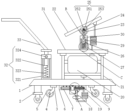
[0032] see Figure 1-5, a rail flaw detection device for rail transit, comprising a base 1, a roller 2 is fixedly installed on one side of the bottom of the base 1, and a fixed frame 3 is fixedly connected to the bottom of the base 1, and a movable shaft 4 is movably socketed on the front of the fixed frame 3 , the outside of the movable shaft 4 is fixedly sleeved with a rail wheel 5, the middle part of the bottom end of the base 1 is fixedly connected with a ...


PUM


Abstract

The invention relates to the technical field of steel rail crack detection devices, and discloses a rail transit steel rail crack detection device which comprises a base. Rollers are fixedly mounted on one side of the bottom of the base, a fixed frame is fixedly connected at the bottom of the base, a movable shaft is movably connected on the front of the fixed frame in a sleeving manner, a steel rail wheel is fixedly connected outside the movable shaft in a sleeving manner, a cross plate is fixedly connected in the middle of the bottom end of the base, a movable groove is formed in the front of the cross plate, and a movable block is movably connected in the movable groove in a sleeving manner. The rail transit steel rail crack detection device is provided with the movable block, a movablespring, a fixed bolt, a fixed hole, a slider, a connecting rod and a fixed nail which are matched, a ultrasonic probe can be adjusted according to detection requirements in the detection process of asteel rail, so that a detection range is widened, a non-detection zone is avoided, the detection effect of the device is improved, an adjusting process is simple and convenient, and time and labor are saved.

Description

technical field [0001] The invention relates to the technical field of rail flaw detection equipment, in particular to a rail flaw detection device for rail transit. Background technique [0002] The rail is the main component of the railway track. Its function is to guide the wheels of the rolling stock, bear the huge pressure of the wheel, and transmit it to the sleeper; the rail must provide a continuous, smooth and least resistance rolling surface for the wheel. In the electrified railway Or in the automatic blocking section, the rail can also be used as a track circuit. The rail can be divided into three types: crane rail (crane rail), heavy rail and light rail based on the approximate weight of kilograms per meter. [0003] The invention with the existing application number 201710840481.0 discloses a full-section flaw detection method and device for rail bottoms in service, including a trolley and a flaw detection structure. The flaw detection structure is set on the b...

Claims


Application Information

Patent Timeline
Patent Type & Authority Applications(China)
IPC IPC(8): B61K9/10
CPCB61K9/10
Inventor 李荣旭
Owner 盐城海诺斯自动化设备有限公司
Why Eureka
Try Eureka