Adjustable delivery-aiding device for medical treatment in obstetrics and gynecology department

A medical and adjustable technology, applied in obstetrics and gynecology equipment and other directions, can solve the problems of inability to adjust the midwifery device, inconvenient use by medical staff, affecting the safety of the fetus, etc., to improve the scope of use and reduce scalp abrasions The effect of cracking and improving mobility

Inactive Publication Date: 2018-10-12
朱沛沛
View PDF0 Cites 1 Cited by
  • Summary
  • Abstract
  • Description
  • Claims
  • Application Information

AI Technical Summary

Problems solved by technology

In the prior art, the most commonly used midwifery devices are midwifery forceps and fetal head suction; when using fetal head suction for midwifery, the safety of the fetus may be affected due to improper control of negative pressure; existing midwifery forceps, When in use, the pliers body is generally placed on the lower edge of the ear pinna on both sides of the baby's head, and the baby's head is buckled by the pliers handle to drag the baby out. This operation is easy to hurt the baby, and it is very difficult for medical staff to use. Inconvenient and sometimes aggravating maternal pain
[0003] The current midwifery device cannot be adjusted and has low safety performance, so there is an urgent need for an adjustable midwifery device for obstetrics and gynecology

Method used


Image

  • Adjustable delivery-aiding device for medical treatment in obstetrics and gynecology department
  • Adjustable delivery-aiding device for medical treatment in obstetrics and gynecology department
  • Adjustable delivery-aiding device for medical treatment in obstetrics and gynecology department

Examples


Embodiment Construction

[0026] The following will clearly and completely describe the technical solutions in the embodiments of the present invention with reference to the accompanying drawings in the embodiments of the present invention. Obviously, the described embodiments are only some, not all, embodiments of the present invention.

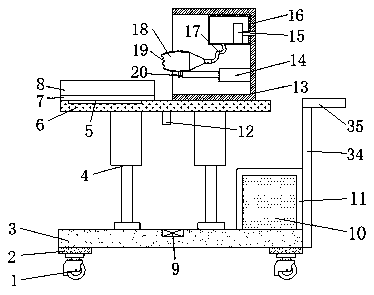
[0027] refer to Figure 1-6 , an adjustable midwifery device for obstetrics and gynecology, including a base 3, a chute is provided on the top outer wall of the base 3, and an electric slide rail 21 is installed and connected to the inner wall of the chute, and the inner walls of the two ends of the electric slide rail 21 are slidingly connected There are two sliders 22, and the top outer walls of the two sliders are connected with a hydraulic cylinder 4 by bolts, and the outer walls of the top of the hydraulic cylinder 4 are connected with the same horizontally placed top plate 6 by bolts, and the outer wall of the top side of the top plate 6 is welded to help The p...


PUM


Abstract

The invention belongs to the technical field of medical devices and particularly provides an adjustable delivery-aiding device for medical treatment in the obstetrics and gynecology department. For solving the problem that a delivery-aiding device is simple in structure and single in function, the following scheme is proposed that the delivery-aiding device comprises a base, wherein a sliding groove is formed in the outer wall of the top of the base, an electric sliding rail is installed and connected to the inner wall of the sliding groove, two slide blocks are slidingly connected to the inner walls of two ends of the electric sliding rail, hydraulic cylinders are connected to the outer walls of the tops of the two slide blocks through bolts, the same horizontally placed top plate is connected to the outer walls of the tops of the hydraulic cylinders through bolts, a delivery-aiding housing is welded to the outer wall of one side of the top of the top plate, and a horizontally arranged electrically controlled telescopic rod is connected to the outer wall of the bottom of one side of the delivery-aiding housing through bolts. The adjustable delivery-aiding device is provided with anegative pressure cover sealing edge, the adsorption range can be widened, the skin contact abrasion is remarkably improved, an adsorption force is uniformly dispersed, decrease of problems such as fetus scalp scratching or tearing caused by suction of a suction apparatus is facilitated, and fetus health is ensured.

Description

technical field [0001] The invention relates to the technical field of medical equipment, in particular to an adjustable midwifery device for obstetrics and gynecology. Background technique [0002] In the process of natural delivery in obstetrics and gynecology, when the baby's head is about to be exposed, the doctor usually needs to use a midwifery device to suck the fetal head out, so as to cooperate with the parturient to drag the baby out of the uterus to ensure the safety of the mother and child. In the prior art, the most commonly used midwifery devices are midwifery forceps and fetal head suction; when using fetal head suction for midwifery, the safety of the fetus may be affected due to improper control of negative pressure; existing midwifery forceps, When in use, the pliers body is generally placed on the lower edge of the ear pinna on both sides of the baby's head, and the baby's head is buckled by the pliers handle to drag the baby out. This operation is easy to...

Claims


Application Information

Patent Timeline
Patent Type & Authority Applications(China)
IPC IPC(8): A61B17/44
CPCA61B17/442
Inventor 朱沛沛
Owner 朱沛沛
Why Eureka
Try Eureka