
Floating dock with fin stabilizers

A floating dock and fin stabilizer technology, which is applied in the direction of reducing ship movement, using hydrofoils to reduce ship movement on the surrounding water surface, and increasing ship stability. It can solve collisions, poor wind and wave resistance of floating docks, etc. problem, to achieve the effect of improving safety, reducing drive energy consumption, and large buffering effect

Active Publication Date: 2018-10-12
ZHEJIANG OCEAN UNIV
View PDF8 Cites 12 Cited by
  • Summary
  • Abstract
  • Description
  • Claims
  • Application Information

AI Technical Summary

Problems solved by technology

[0002] The floating dock has a huge concave-shaped cabin with walls on both sides and open front and rear ends. It is a trough-shaped flat-bottomed boat with a special structure. It is used in the maintenance and construction of offshore ships. Due to the large draft when the floating dock sinks, it needs sufficient water depth, but the water depth in the offshore is relatively shallow, so it needs to be installed in a far sea area, and the wind and waves in the far sea area are relatively large. When needed When the repaired ship enters and exits the floating dock, the floating dock and the maintenance ship will sway to a certain extent, which may cause the two to collide and cause certain marine accidents. Moreover, the structural design of the front and rear openings of the floating dock makes the floating dock more resistant to wind and waves. Difference

Method used


Image

  • Floating dock with fin stabilizers
  • Floating dock with fin stabilizers
  • Floating dock with fin stabilizers

Examples


Embodiment Construction

[0035] The following are specific embodiments of the present invention and in conjunction with the accompanying drawings, the technical solutions of the present invention are further described, but the present invention is not limited to these embodiments.

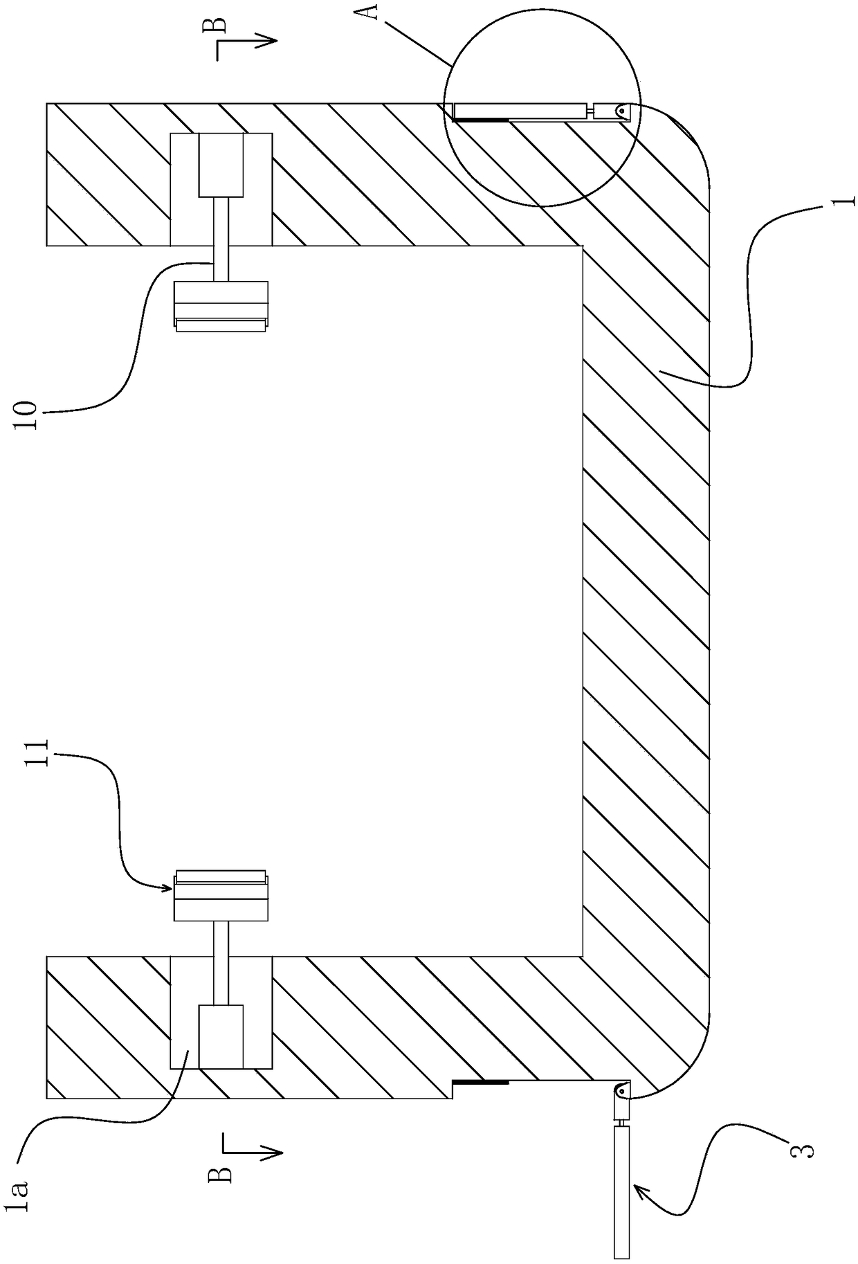
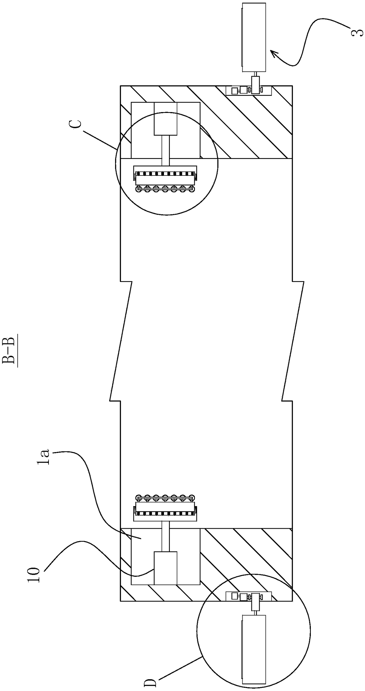
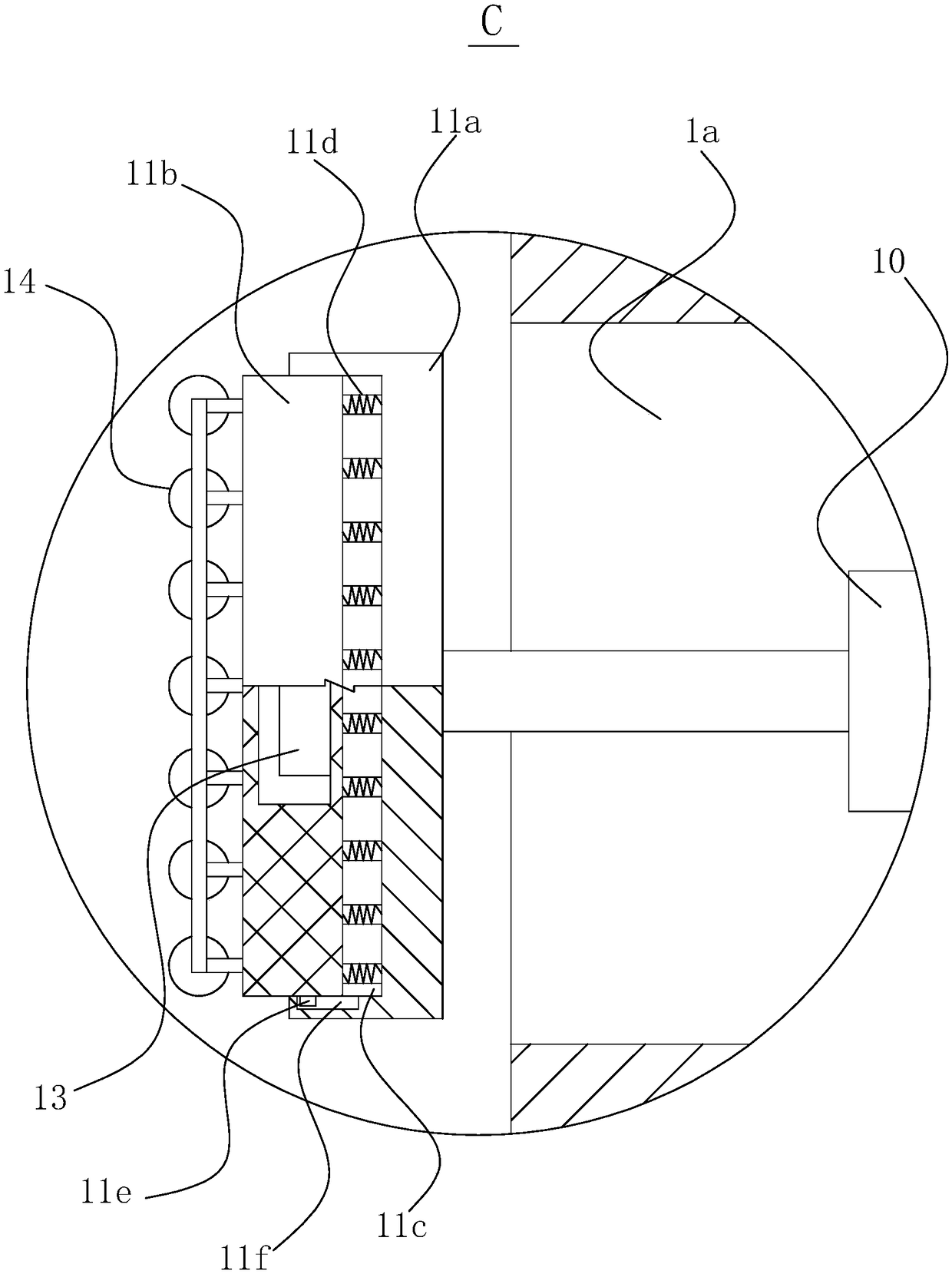
[0036] refer to Figures 1 to 4 , a floating dock with fin stabilizers, comprising a floating dock body 1, a plurality of installation grooves-1a are provided on both sides of the floating dock body 1 along the length direction, and several installation grooves-1a Hydraulic cylinders 10 are arranged inside, and the piston rods of the hydraulic cylinders 10 are arranged horizontally. The end of the piston rods of the hydraulic cylinders 10 is provided with an anti-collision mechanism 11. When the piston rods of the hydraulic cylinders 10 are stretched, there is at least one position, The anti-collision mechanism 11 is located in the installation groove one 1a, and the anti-collision mechanism 11 includes a bottom plate 11a,...


PUM


Abstract

The invention provides a floating dock with fin stabilizers and belongs to the technical field of marine equipment. The floating dock comprises a floating dock body. Multiple first installation grooves are formed in the two sides in the floating dock body in the length direction. Hydraulic oil cylinders are arranged in the multiple first installation grooves. Piston rods of the hydraulic oil cylinders are horizontally arranged. Anti-collision mechanisms are arranged at the ends of the piston rods of the hydraulic oil cylinders. Each anti-collision mechanism comprises a bottom board. The back faces of the bottom boards are fixedly connected with the ends of the piston rods of the hydraulic oil cylinders. Grooves are formed in the front faces of the bottom boards. Buffer boards are arrangedin the grooves in a sliding mode. Multiple buffer springs are arranged between the front face of each groove and the back face of the corresponding buffer board. The front faces of the buffer boards are provided with multiple rolling wheels through supports. The rolling wheels are further provided with power generation devices capable of generating power through the rolling wheels. The anti-collision mechanisms can prevent a ship from colliding with the floating dock when sailing in and out of the dock, rolling contact between the ship and the rolling wheels on the anti-collision mechanisms can be used for generating power, energy is saved, and the floating dock is environment-friendly.

Description

technical field [0001] The invention belongs to the technical field of ship equipment, and relates to a floating dock with fin stabilizers. Background technique [0002] The floating dock has a huge concave-shaped cabin with walls on both sides and open front and rear ends. It is a trough-shaped flat-bottomed boat with a special structure. It is used in the maintenance and construction of offshore ships. Due to the large draft when the floating dock sinks, it needs sufficient water depth, but the water depth in the offshore is relatively shallow, so it needs to be installed in a far sea area, and the wind and waves in the far sea area are relatively large. When needed When the repaired ship enters and exits the floating dock, the floating dock and the maintenance ship will sway to a certain extent, which may cause the two to collide and cause certain marine accidents. Moreover, the structural design of the front and rear openings of the floating dock makes the floating dock ...

Claims


Application Information

Patent Timeline
IPC IPC(8): B63B39/06B63B43/18H02K7/18
CPCB63B39/062B63B43/18H02K7/1853
Inventor 张华吕棋
Owner ZHEJIANG OCEAN UNIV
Learn More