Traction device of knitting machine

A technology of a pulling device and a knitting machine, applied in knitting, weft knitting, warp knitting, etc., which can solve the problems of easy deformation of fabrics, loss of rubber layer, and inability to pull fabrics

Active Publication Date: 2018-10-12
NINGBO CIXING
View PDF7 Cites 6 Cited by
  • Summary
  • Abstract
  • Description
  • Claims
  • Application Information

AI Technical Summary

Problems solved by technology

[0002] At present, most of the pulling devices of knitting machines use roller devices, but the roller devices are aimed at pulling the entire fabric at the same time, and cannot achieve selective pulling of the fabric, especially on fully formed machines. In addition, the rubber layer in the roller has a certain weariness, and the fabric will be easily deformed when pulled to a certain extent, which increases the scrap rate

Method used


Image

  • Traction device of knitting machine
  • Traction device of knitting machine
  • Traction device of knitting machine

Examples


Embodiment Construction

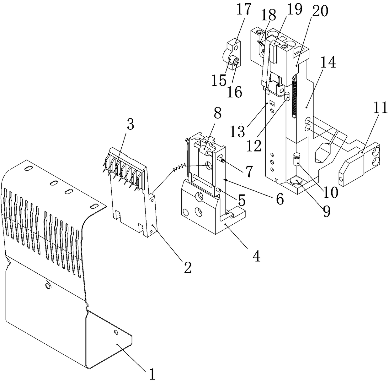
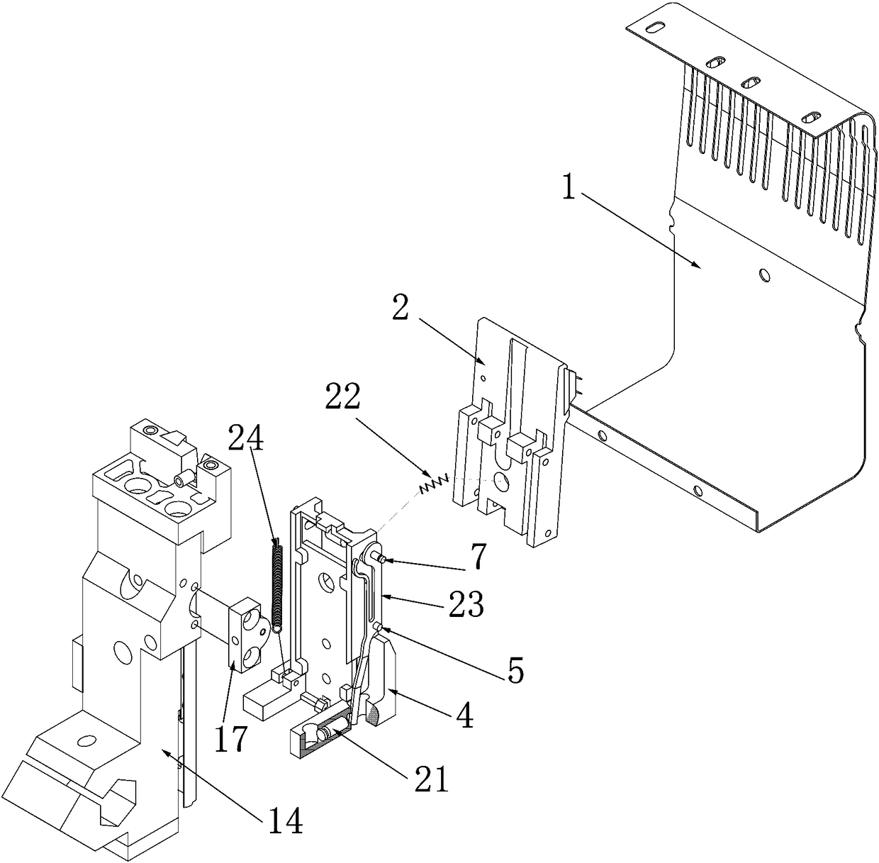
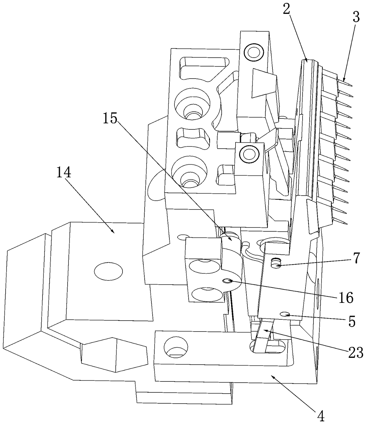
[0021] See attached picture. The pulling device of this embodiment is composed of several rake-type pulling mechanisms on both sides, and each rake-type pulling mechanism is independent, and some of the rake-type pulling mechanisms can be freely selected for action. Each rake-type pulling mechanism includes a claw seat 2, a lifting seat 4 and a fixed seat 14;

[0022] Above the front side of the gripper seat 2 is provided with a gripper 3 composed of several sheet needles, the gripper 3 can complete the pulling action without causing damage to the knitted fabric; the front end of the gripper seat 2 is also provided with a guard plate 1. There are several long grooves on the guard plate for the claws to move. The guard plate 1 is installed on the fixing seat 14 through the guard plate support 11 to protect the fabric and the claws. A linear bearing seat 6 is installed on the lifting seat 4, and the linear bearing seat 6 and the fixed seat 14 are connected by a linear bearing 1...


PUM


Abstract

The invention discloses a traction device of a knitting machine. The traction device comprises multiple traction mechanisms arranged oppositely, wherein each traction mechanism comprises a gripper base with a gripper, a lifting seat and a fixing seat. A linear bearing seat is installed on the lifting seat, a first rotary shaft and a second rotary shaft are arranged on the linear bearing seat, thefirst rotary shaft is arranged in a long groove hole formed in the upper portion of the linear bearing seat, and the gripper base is installed on the two rotary shafts. A first pneumatic piston assembly driving the first rotary shaft to move in the long groove hole is arranged on the side face of the lifting seat, the first rotary shaft drives the corresponding gripper base to rotate around the second rotary shaft. A lifting tension spring for connecting the fixing seat and the lifting seat is arranged on the side face of the fixing seat, and a second pneumatic piston for pushing the corresponding lifting seat to move down is also arranged on the side face of the corresponding fixing seat. The traction device is provided with multiple independent traction mechanisms, the traction mechanisms can be freely selected to act and achieve double-side traction, single-side traction or certain-part traction on one side, selective fabric traction is achieved, and the traction device is speciallysuitable for completely formed knitting machines.

Description

technical field [0001] The invention belongs to the technical field of knitting machines, in particular to a pulling device of a knitting machine. Background technique [0002] At present, most of the pulling devices of knitting machines use roller devices, but the roller devices are aimed at pulling the entire fabric at the same time, and cannot achieve selective pulling of the fabric, especially on fully formed machines. In addition, the rubber layer in the roller has a certain weariness, and the fabric will be easily deformed when pulled to a certain extent, which increases the scrap rate. Contents of the invention [0003] The object of the present invention is to provide a pulling device of a knitting machine capable of selectively pulling fabrics and adjusting the pulling force according to requirements. [0004] For this reason, the technical solution of the present invention is: a pulling device of a knitting machine, which is characterized in that it includes a p...

Claims


Application Information

Patent Timeline
Patent Type & Authority Applications(China)
IPC IPC(8): D04B15/88D04B27/34
CPCD04B15/88D04B27/34
Inventor 孙平范徐卫东胡跃勇陶伯明
Owner NINGBO CIXING
Why Eureka
Try Eureka