Water work support device and method

A technology of support device and support method, applied in water conservancy projects, underwater structures, buildings, etc., can solve the problems of poor wind and wave resistance, long construction period, and poor stability, and achieve strong wind and wave resistance and short construction period. , good stability

Active Publication Date: 2020-09-29
德州双航包装制品有限公司
View PDF3 Cites 0 Cited by
  • Summary
  • Abstract
  • Description
  • Claims
  • Application Information

AI Technical Summary

Problems solved by technology

[0003] The purpose of the invention is to overcome the disadvantages of long construction period, high cost, inconvenient movement, poor stability, and poor ability to resist wind and waves of the supporting device for water operations in the prior art, and to provide a pile foundation that is stable, easy to install and disassemble Convenient water operation supporting device and method

Method used


Image

  • Water work support device and method
  • Water work support device and method
  • Water work support device and method

Examples


Embodiment 1

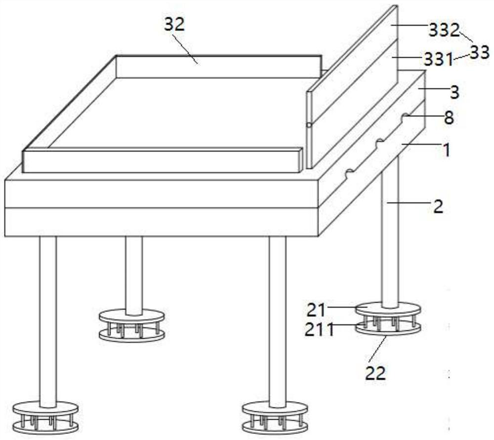
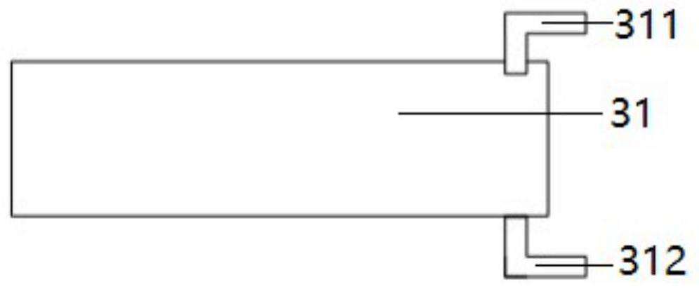
[0048] Such as figure 1 , figure 2 , Figure 5The shown embodiment is a support device for water work, including a support frame 1, four support piles 2 arranged at the lower part of the support frame, and a work platform 3 arranged on the support frame; a ballast water tank 31 is provided in the work platform, A water inlet pipe 311 and an outlet pipe 312 are arranged on the ballast water tank, a water pump 35 and a vacuum pump 36 are arranged on the water inlet pipe, a solenoid valve 3011 is arranged on the water inlet pipe and the water outlet pipe, and a pressing plate 21 is arranged at the lower end of each supporting pile. The lower surface is provided with 6 columns 211, and each column is provided with permanent magnets 2111, and the lower part of the ground at the bottom of the water is provided with 4 connecting plates 22 corresponding to the positions of each pressing plate, and each connecting plate is provided with 6 Each positioning pin 221 is respectively use...

Embodiment 2

[0064] Embodiment 2 comprises all structures and method parts in embodiment 1, as figure 1 As shown, the work platform of embodiment 2 is also provided with a windshield 33, the windshield includes a lower rectangular plate 331 and an upper rectangular plate 332, the lower rectangular plate and the upper rectangular plate are connected by a rotating shaft, and the rotating shaft is provided with a Drive the rotating motor 334 that the upper rectangular plate rotates along the lower rectangular plate, as Figure 5 As shown, the rotating motor is electrically connected to the controller.

[0065] (8-1) The operator obtains the current wind speed data information through the network, and the wind speed threshold is set to K; K is 10 m / s;

[0066] (8-2) When the wind speed > K, the operator controls the rotation motor to work through the controller, so that the angle between the upper rectangular plate and the lower rectangular plate is 180°, and the upper rectangular plate and t...

Embodiment 3

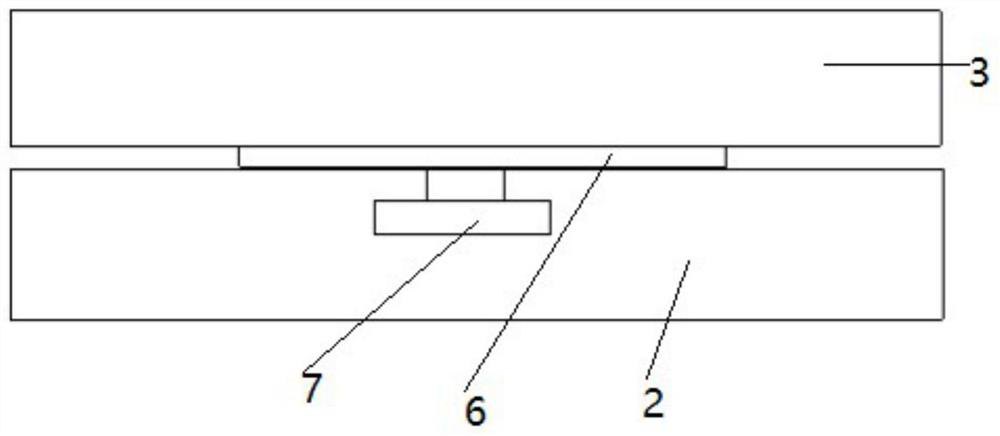
[0070] Embodiment 3 comprises all structures and method parts of embodiment 2, as image 3 , Figure 5 As shown, the working platform of embodiment 3 is provided with wind direction anemometer 5, and the upper surface of support frame is provided with turntable 6, and turntable is connected with work platform, and support frame is provided with turntable motor 7, and work platform lower surface is provided with 3 Parallel diversion grooves 8, the windshields are perpendicular to each diversion groove, and the wind direction anemometer and the turntable motor are all electrically connected to the controller.

[0071] Steps (8-1) to (8-3) are replaced by the following steps:

[0072] (9-1) The wind direction anemometer detects the current wind direction and wind speed, and the wind speed threshold is set to K;

[0073] (9-2) When the wind speed > K, the operator controls the rotation motor to work through the controller, so that the angle between the upper rectangular plate an...


PUM


Abstract

The invention discloses an on-water operation support device and method. The on-water operation support device comprises a support frame, N support columns arranged at the lower part of the support frame, and an operating platform arranged on the support frame; the operating platform is internally provided with a ballast water tank which is provided with a water inlet pipe and a water outlet pipe,and the water inlet pipe is provided with a water pump and a vacuum pump; the water inlet pipe and the water outlet pipe are both provided with solenoid valves, and the lower end of each support column is provided with a pressing plate of which the lower surface is provided with M vertical columns; and each vertical column is internally provided a permanent magnet, and the ground lower part of awater bottom is internally provided with N connecting plates corresponding to the pressing plates separately. The on-water operation support device has the characteristics of stable pile foundation, easy installation and removal, and high storm resistance and stability.

Description

technical field [0001] The invention relates to the technical field of underwater operation equipment, in particular to a support device and method for underwater operations with stable pile foundation and convenient installation and disassembly. Background technique [0002] Support devices for water operations include fixed support devices and floating support devices. The fixed support device has a durable structure and low maintenance costs. However, it has the problems of long construction period, high cost, and inconvenient movement; the floating support device has poor stability. , the problem of poor ability to resist wind and waves. Contents of the invention [0003] The purpose of the invention is to overcome the disadvantages of long construction period, high cost, inconvenient movement, poor stability, and poor ability to resist wind and waves of the supporting device for water operations in the prior art, and to provide a pile foundation that is stable, easy t...

Claims


Application Information

Patent Timeline
Patent Type & Authority Patents(China)
IPC IPC(8): E02B17/00
CPCE02B17/00E02B2017/0056
Inventor 不公告发明人
Owner 德州双航包装制品有限公司
Why Eureka
Try Eureka