
Heat exchange device based on inclined columns and heat exchange method thereof

A technology of heat exchange device and slanted column, which is applied in the field of heat exchange device based on slanted column, can solve the problems of slow heat exchange speed of heating air, slow temperature rise, uneven temperature distribution, etc., so as to improve heat exchange efficiency and improve uniformity sexual effect

Active Publication Date: 2018-10-16
HANGZHOU DIANZI UNIV
View PDF5 Cites 0 Cited by
  • Summary
  • Abstract
  • Description
  • Claims
  • Application Information

AI Technical Summary

Problems solved by technology

In daily life, the heat transfer speed of the heating system we use is relatively slow, and the temperature distribution is uneven, so this deficiency has brought about the failure of the heating device to achieve the expected effect.
The heating heat exchange efficiency of the existing heat exchange device is relatively low, which makes the indoor temperature rise slowly

Method used


Image

  • Heat exchange device based on inclined columns and heat exchange method thereof
  • Heat exchange device based on inclined columns and heat exchange method thereof
  • Heat exchange device based on inclined columns and heat exchange method thereof

Examples


Embodiment 1

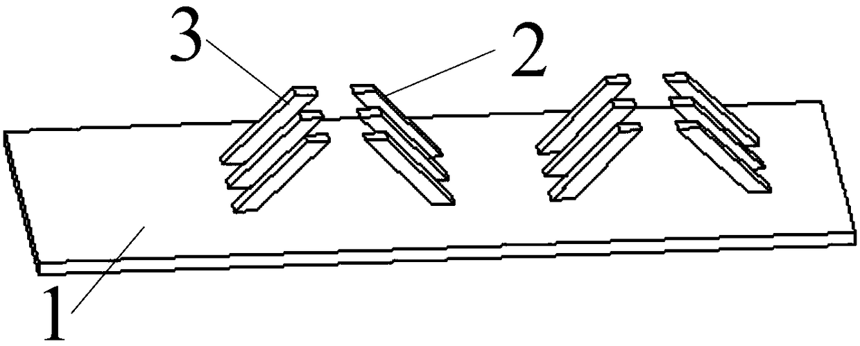
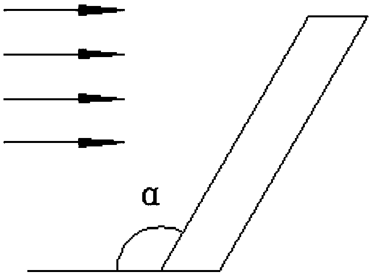
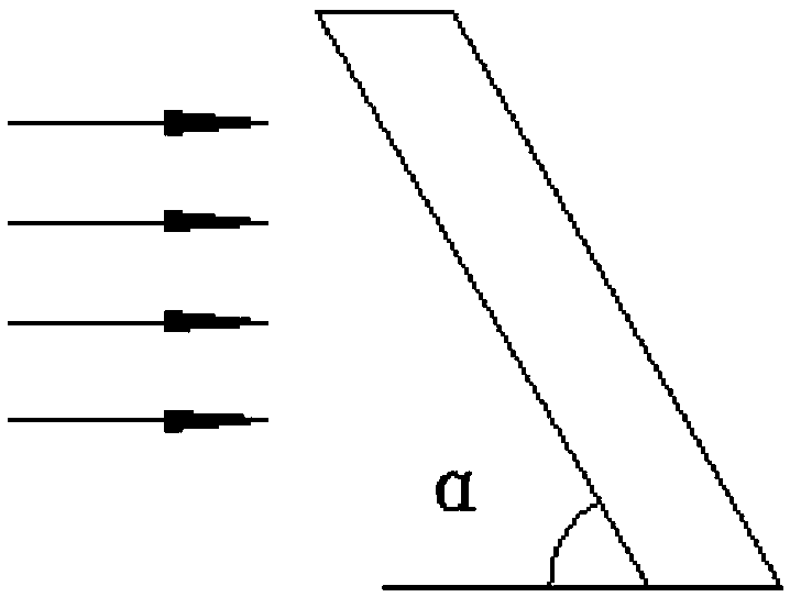
[0044] The front inclined column 3 is shown in Figure 2(a), and the rear inclined column 1 is shown in Figure 2(b). Both the front inclined column 3 and the rear inclined column 2 are oblique quadrangular prisms. The angle between the central axis of the front inclined column and the central axis of the rear inclined column and the installation side of the frame 1 is α, and α is 30°, 40°, 50° or 60°. The cross section of the front inclined column 3 and the rear inclined column 2 is a rectangle whose length is equal to c and width is equal to d, and 5mm≤d≤40mm.

[0045] In this embodiment, α is 50°, c is 25mm, h is 400mm, f is 200mm, s is 900mm, and there is an airflow of 4m / s from the inlet end of the frame to the outlet end, the heat transfer effect simulation diagram is as follows Figure 4(b), the simulated streamline diagram at the front inclined column is shown in Figure 3(b), and the simulated streamline diagram at the rear inclined column is shown in Figure 3(c).

[00...

Embodiment 2

[0049] The front inclined column 3 is shown in Figure 2(c), and the rear inclined column 1 is shown in Figure 2(d). Both the front inclined column 3 and the rear inclined column 2 adopt curved quadrangular prisms. The cross sections of the front inclined column 3 and the rear inclined column 2 are rectangular, and the center line is an arc segment. The concave sides of the front inclined column 3 and the rear inclined column 2 are both facing the air outlet end of the frame 1 . The angle between the line connecting the two ends of the center line of the front inclined column and the line connecting the two ends of the center line of the rear inclined column and the installation side of the frame 1 is α, and α is 50°. The cross section of the front inclined column 3 and the rear inclined column 2 is a rectangle whose length is equal to c and width is equal to d, and 5mm≤d≤40mm.

[0050] In this embodiment, c is 25mm, h is 400mm, f is 200mm, and s is 900mm, and when there is a...

Embodiment 3

[0054] The front inclined column 3 is shown in Figure 2(c), and the rear inclined column 1 is shown in Figure 2(f). Both the front inclined column 3 and the rear inclined column 2 adopt curved quadrangular prisms. The cross sections of the front inclined column 3 and the rear inclined column 2 are rectangular, and the center line is an arc segment. The concave side of the front inclined column 3 faces the air outlet end of the frame 1 . The concave side of the rear inclined column 2 faces the air intake end of the frame 1 . The angle between the line connecting the two ends of the center line of the front inclined column and the line connecting the two ends of the center line of the rear inclined column and the installation side of the frame 1 is α, and α is 50°. The cross section of the front inclined column 3 and the rear inclined column 2 is a rectangle whose length is equal to c and width is equal to d, and 5mm≤d≤40mm.

[0055] In this embodiment, c is 25mm, h is 400mm,...


PUM


Abstract

The invention discloses a heat exchange device based on inclined columns and a method of the heat exchange device. The heater heat exchange efficiency of an existing heat exchange device is relativelylow. The heat exchange device based on the inclined columns comprises a frame and inclined column sets. One end of the frame is an air inlet end, and the other end of the frame is an air outlet end.The m inclined column sets are arranged. The m inclined column sets are arranged on the installation side face of the frame in sequence in the length direction of the frame. Each inclined column set includes n front inclined columns and n rear inclined columns. The inner ends of the n front inclined columns and the inner ends of the n rear inclined columns of each inclined column set are fixedly connected with the installation side face of the frame. The n front inclined columns and the n rear inclined columns of each inclined column set align to each other in the width direction of the frame.Each front inclined column is located on the side, close to the air inlet end of the frame, of the corresponding rear inclined column. The outer end of each front inclined column is inclined towardsthe air outlet end of the frame, and the outer end of each rear inclined column is inclined towards the air inlet end of the frame. By the adoption of the heat exchange device based on the inclined columns and the method of the heat exchange device, the convection of the air flow in the heat exchange device can be improved, and the heat exchange efficiency of the heat exchange device is improved.

Description

technical field [0001] The invention belongs to the technical field of heat exchange, and in particular relates to a heat exchange device based on an inclined column and a heat exchange method thereof. Background technique [0002] Due to the wide range of our country, the temperature difference between the north and the south is very large. The temperature in the southern area is relatively high, and air conditioning is generally used, while the temperature in the northern area is particularly cold, and heating is generally used. In daily life, the heat transfer speed of the heating system we use is slow, and the temperature distribution is uneven, so this deficiency has brought about the failure of the heating device to achieve the expected effect. The heating heat exchange efficiency of the existing heat exchange device is relatively low, so that the indoor temperature rise rate is slow. Contents of the invention [0003] The purpose of the present invention is to prov...

Claims


Application Information

Patent Timeline
IPC IPC(8): F28D1/00F24D19/00
CPCF24D19/00F28D1/00
Inventor 聂欣柯文杰吕明
Owner HANGZHOU DIANZI UNIV
Learn More