Plant extraction equipment with efficient liquid-residue separation function
A technology for liquid residue separation and plant extraction, applied in solid solvent extraction, chemical/physical process, dissolution and other directions, can solve the problem that the degree of solvent convection cannot be greatly increased, the degree of solvent convection cannot be greatly improved, and cannot be maximized. To improve the leaching effect and other issues, to achieve the effect of speeding up the leaching rate, improving the leaching effect, and improving the pressure effect
- Summary
- Abstract
- Description
- Claims
- Application Information
AI Technical Summary
Problems solved by technology
Method used
Image
Examples
Embodiment 1
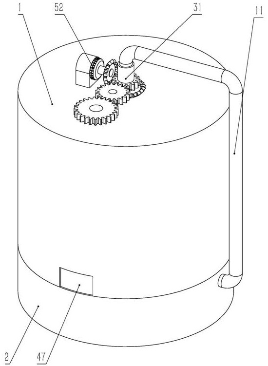
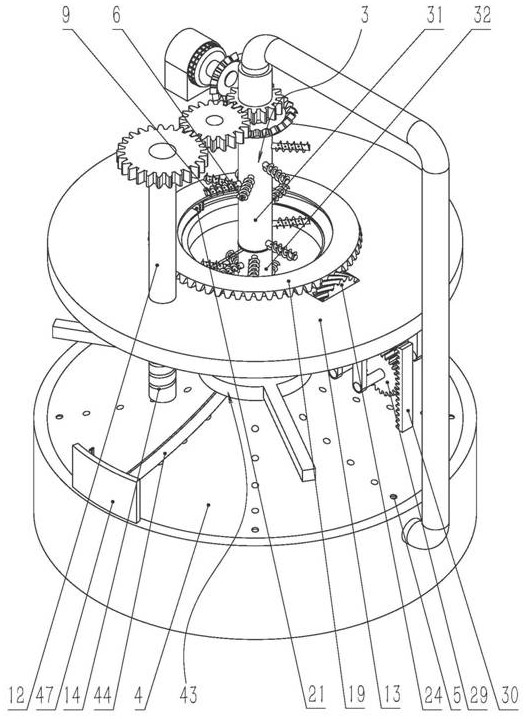
[0031] Embodiment 1, the technical solution it solves is, a kind of plant extraction equipment with high-efficiency liquid slag separation function, comprises vertical leaching barrel 1 and heating barrel 2, and leaching barrel 1 is placed on heating barrel 2 and leaching The openings of the barrel 1 and the heating barrel 2 are opposite, the leaching barrel 1 and the heating barrel 2 are coaxially sealed and connected, and the coaxial sealing and rotating connection of the leaching barrel 1 is connected with the rotating shaft 3 placed in the leaching barrel 1, and the lower end of the rotating shaft 3 A conical body 4 with an upward apex is coaxially connected. The cone 4 is placed at the bottom of the leaching barrel 1 and separates the leaching barrel 1 from the heating barrel 2. A plurality of filter holes 5 are evenly distributed on the cone 4. The leaching The barrel 1 and the heating barrel 2 are connected through the filter hole 5, the outer edge of the cone 4 is in sl...
Embodiment 2
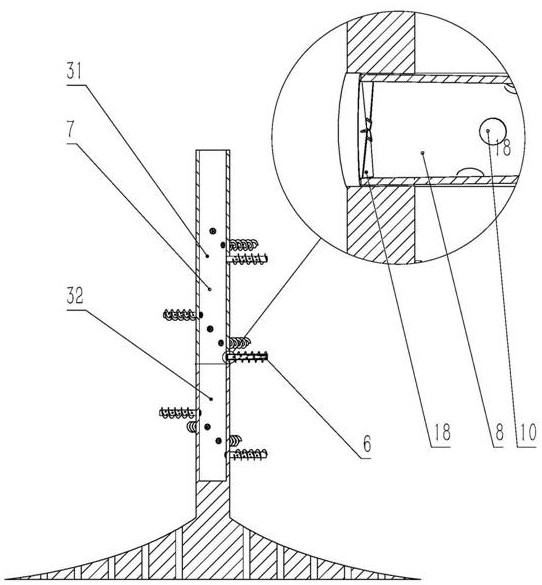
[0035] Embodiment 2, on the basis of Embodiment 1, the end of the rotating shaft 6 close to the rotating shaft has a plurality of fan blades 18 uniformly distributed in the air passage 8, and the plurality of fan blades 18 constitute a shaftless fan .
[0036] When in use, the vaporized leaching solvent is discharged into the air passage 8 of the rotating shaft 6 under the action of the air pump, and the vaporized leaching solvent pushes the fan blade 18 to rotate, so that the rotating shaft 6 rotates with the fan blade 18, and the rotating shaft drives The rotation of the helical blades 9 realizes the effect of the external force forcibly driving the helical blades 9 to stir the botanical medicinal materials, and prevents the botanical medicinal materials from blocking the gap between two adjacent helical blades 9 so that the helical blades 9 cannot rotate.
Embodiment 3
[0037] Embodiment 3, on the basis of Embodiment 1, the transmission mechanism includes a first bevel gear 19 placed above the pressing plate 17 and coaxially connected with the pressing plate 13, between the first bevel gear 19 and the pressing plate 17 Slidingly connected along the radial direction of the pressure plate 13, the end of the pressure piece 17 away from the axis of the pressure plate 13 has a stopper 20, and the lower end of the first bevel gear 19 has two stoppers that match the stopper 20 and are respectively placed on both sides of the stopper 20 Block 21, the space between the two limiting blocks 21 forms a chute 22, the length direction of the chute 22 is along the radial direction of the pressure plate 13, the stopper 20 is placed in the chute 22 and can be moved along the length direction of the chute 22 Sliding, the inner diameter of the first bevel gear 19 is greater than the inner diameter of the pressing plate 13, and the pressing plate 13 is rotatably ...
PUM
 Abstract
Description
Claims
Application Information
 - R&D
- Intellectual Property
- Life Sciences
- Materials
- Tech Scout
- Unparalleled Data Quality
- Higher Quality Content
- 60% Fewer Hallucinations
Browse by: Latest US Patents, China's latest patents, Technical Efficacy Thesaurus, Application Domain, Technology Topic, Popular Technical Reports.
© 2025 PatSnap. All rights reserved.Legal|Privacy policy|Modern Slavery Act Transparency Statement|Sitemap|About US| Contact US: help@patsnap.com


