A method for establishing a depth domain construction model

A structural model and depth-domain technology, applied to seismology, measuring devices, instruments, etc. for logging records, can solve the problems that cannot meet the needs of prediction and interpretation, and the structural accuracy of the depth domain cannot be effectively resolved.

Active Publication Date: 2018-10-16
CHINA PETROLEUM & CHEM CORP +1
View PDF3 Cites 8 Cited by
  • Summary
  • Abstract
  • Description
  • Claims
  • Application Information

AI Technical Summary

Problems solved by technology

[0006] Cao Danping (2008) based on the analysis of the characteristics of the depth domain data, used the regional velocity and tomographic imaging velocity to convert the crosswell seismic data in the depth domain to the time domain for research, and established the relationship between the crosswell seismic data and the ground surface by coarsening and reducing the frequency. The similarity between seismic data provides an understanding of the low-frequency reflection characteristics of cross-well seismic, and the reflection characteristics of cross-well seismic data are established by combining the calibration of well side channel synthetic seismic records, which accurately explains the reflection horizon of cross-well seismic (Cao Danping, Yin Xingyao, Zhang Fanchang, et al. Research and Application of Fine Interpretation Methods f

Method used


Image

  • A method for establishing a depth domain construction model
  • A method for establishing a depth domain construction model
  • A method for establishing a depth domain construction model

Examples


Embodiment Construction

[0044] The present invention will be described in more detail below with reference to the accompanying drawings. Although preferred embodiments of the invention are shown in the drawings, it should be understood that the invention may be embodied in various forms and should not be limited to the embodiments set forth herein. Rather, these embodiments are provided so that this disclosure will be thorough and complete, and will fully convey the scope of the invention to those skilled in the art.

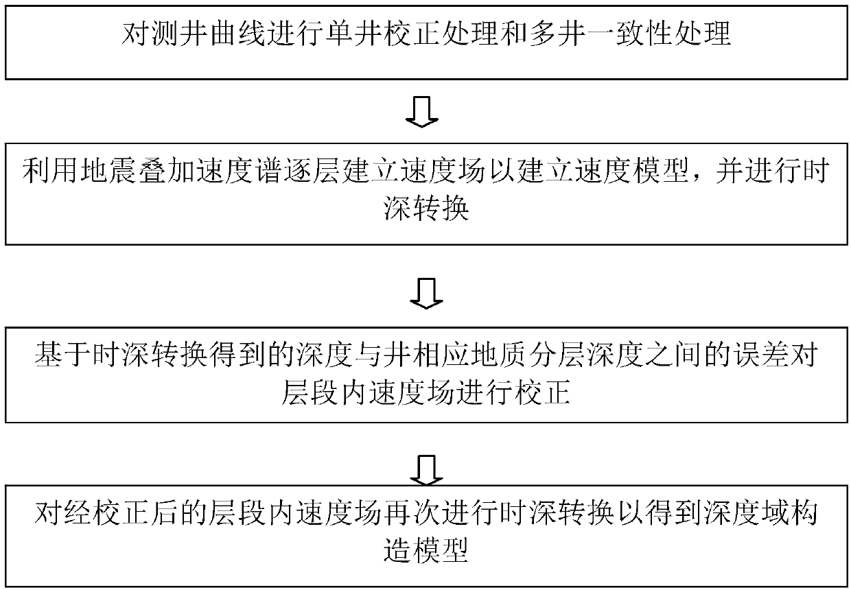
[0045] figure 1 It is a flowchart of a method for establishing a depth domain construction model according to an embodiment of the present invention. The method may include the steps of:

[0046] (1) Perform single-well correction processing and multi-well consistency processing on the logging curve.

[0047] Well logging curves are measured curves of velocity, density, natural gamma ray, etc., and these measured curves are subjected to strict single-well correction processing and m...


PUM


Abstract

The invention discloses a method for establishing a depth domain construction model. The method includes the following steps: single well correction processing and multi-well consistency processing are performed on the logging curve line; the velocity field is established layer by layer by utilizing the seismic stack velocity spectrum to establish the speed model, and time depth conversion is performed; correction is performed on the velocity field in the interval based on the error between the depth obtained by the time depth conversion and the corresponding geology layering depth of the well; and the time depth conversion is performed on the velocity field in the interval after correction again to obtain the depth domain construction model. Two aspects of the accuracy of the time domainconstruction interpretation and the rationality of the time depth conversion velocity model are improved, and the fine degree of the depth domain construction is improved.

Description

technical field [0001] The invention relates to the technical field of oil geophysics, and more specifically, to a method for establishing a depth domain structure model. Background technique [0002] In traditional structural interpretation work, traces are typically performed in seismic waveforms and variable density sections. However, in strata with thin interbeds and strong lateral heterogeneity, due to the influence of seismic reflection structure and tuning and other factors, there will be many problems in the horizon interpretation of the reservoir, and the multi-solution is strong. There may be deviations or even errors in the interpretation of the structure of the waveform. At the same time, due to the uneven distribution of the spatial velocity field, the established velocity model cannot objectively reflect the morphological characteristics of the underground structure, thus misleading the selection of traps and the deployment of well locations. The invention ca...

Claims


Application Information

Patent Timeline
IPC IPC(8): G01V1/50
CPCG01V1/50G01V2210/665
Inventor 武丽刘振峰张珺
Owner CHINA PETROLEUM & CHEM CORP
Why Eureka
Try Eureka