Power supplying apparatus, power supplying control apparatus, and power supplying control method

A technology for power supply and control equipment, applied in the direction of electrical components, data processing power supply, battery data exchange, etc., can solve problems such as coupling disablement

Pending Publication Date: 2018-10-16
RENESAS ELECTRONICS CORP
View PDF5 Cites 1 Cited by
  • Summary
  • Abstract
  • Description
  • Claims
  • Application Information

AI Technical Summary

Problems solved by technology

When the power cannot be supplied, the coupling to the new device is disabled

Method used


Image

  • Power supplying apparatus, power supplying control apparatus, and power supplying control method
  • Power supplying apparatus, power supplying control apparatus, and power supplying control method
  • Power supplying apparatus, power supplying control apparatus, and power supplying control method

Examples


Embodiment 2

[0091] The present embodiment will describe a specific example for changing the priority of power supply for each power receiving device. Incidentally, although a plurality of specific examples for changing the priority will be described as being divided into some in the following description, specific examples may also be combined as appropriate.

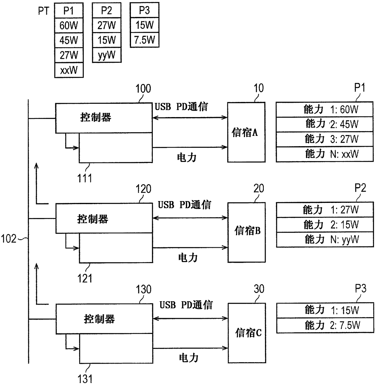
[0092] First, an example in which priorities are changed by user operations will be described. will use Figure 7 The configuration and operation of the power supply device 100 will be described. Figure 7 is a diagram for describing the configuration of the power supply device 100 and its operation. Figure 8 is a diagram showing a change in power receiving capability selected from a table of power distribution.

[0093] First, the configuration of the power supply device 100 according to the present embodiment will be described. Such as Figure 7 As shown in , in the second embodiment, an interface 200 is added to the power ...


PUM


Abstract

The invention aims to provide a power supplying control apparatus, a power supplying apparatus, and a power supplying control method which control power supply appropriately. A power supplying apparatus according to the present embodiment is equipped with a plurality of ports corresponding to a USB (Universal Serial Bus) PD (Power Delivery) standard, a plurality of electric power supplying circuits which are provided corresponding to the ports and supply power to power receiving devices coupled to the ports, and a controller which holds a table of power profiles to which power receiving capabilities for each power receiving device are set, and controls the electric power supplying circuits, based on the table in such a manner that total supply power supplied from the electric power supplying circuits does not exceed a prescribed value.

Description

[0001] Cross References to Related Applications [0002] The disclosure of Japanese Patent Application No. 2017-063033 filed on March 28, 2017 including specification, drawings and abstract is hereby incorporated by reference in its entirety. technical field [0003] The present invention relates to a power supply device, a power supply control device and a power supply control method. Background technique [0004] A USB communication control system conforming to the USB (Universal Serial Bus) standard has been disclosed in Patent Document 1. The USB communication control system is equipped with a host device, a hub device, and a device device. A device device that draws 500mA is defined as a high power device, and a USB device that draws 100mA is defined as a low power device. [0005] A hub controller for a hub device has a function of performing power monitoring and regulation. The hub device supplies 500mA taken from the host device to the group of device devices coup...

Claims


Application Information

Patent Timeline
IPC IPC(8): G06F1/26
CPCG06F1/263G06F1/266G06F1/3206H02M3/156H02J7/00041H02J7/0013H02M1/009
Inventor 武藤贵一
Owner RENESAS ELECTRONICS CORP
Why Eureka
Try Eureka