
Sensor and monitoring system employing sensor

A monitoring system and sensor technology, used in instruments, alarms, anti-theft alarms, etc., can solve problems such as affecting the appearance, affecting the use of sensors, and sensor failure, achieving the effect of convenient installation and maintenance, and eliminating the need for wiring and wiring.

Active Publication Date: 2018-10-16
AMBIT MICROSYSTEMS (SHANGHAI) LTD +1
View PDF8 Cites 0 Cited by
  • Summary
  • Abstract
  • Description
  • Claims
  • Application Information

AI Technical Summary

Problems solved by technology

[0003] Most of the existing sensors are powered by electricity. Generally, they use cables to connect to the power supply or use batteries. When using cables to connect to the power supply, it is necessary to plan the wiring when building the house. If the wiring of the sensor is not planned when building the house It will cause the sensor cable to be exposed and affect the appearance; when using the battery, the battery needs to be replaced regularly to avoid affecting the use of the sensor. It is necessary to check whether the battery is charged frequently, which will cause a lot of inconvenience

Method used


Image

  • Sensor and monitoring system employing sensor
  • Sensor and monitoring system employing sensor
  • Sensor and monitoring system employing sensor

Examples


Embodiment Construction

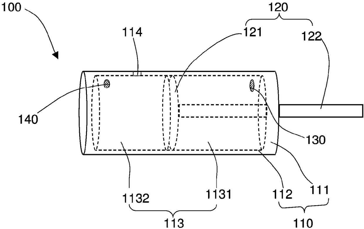
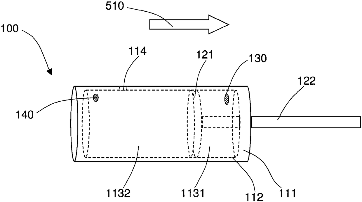
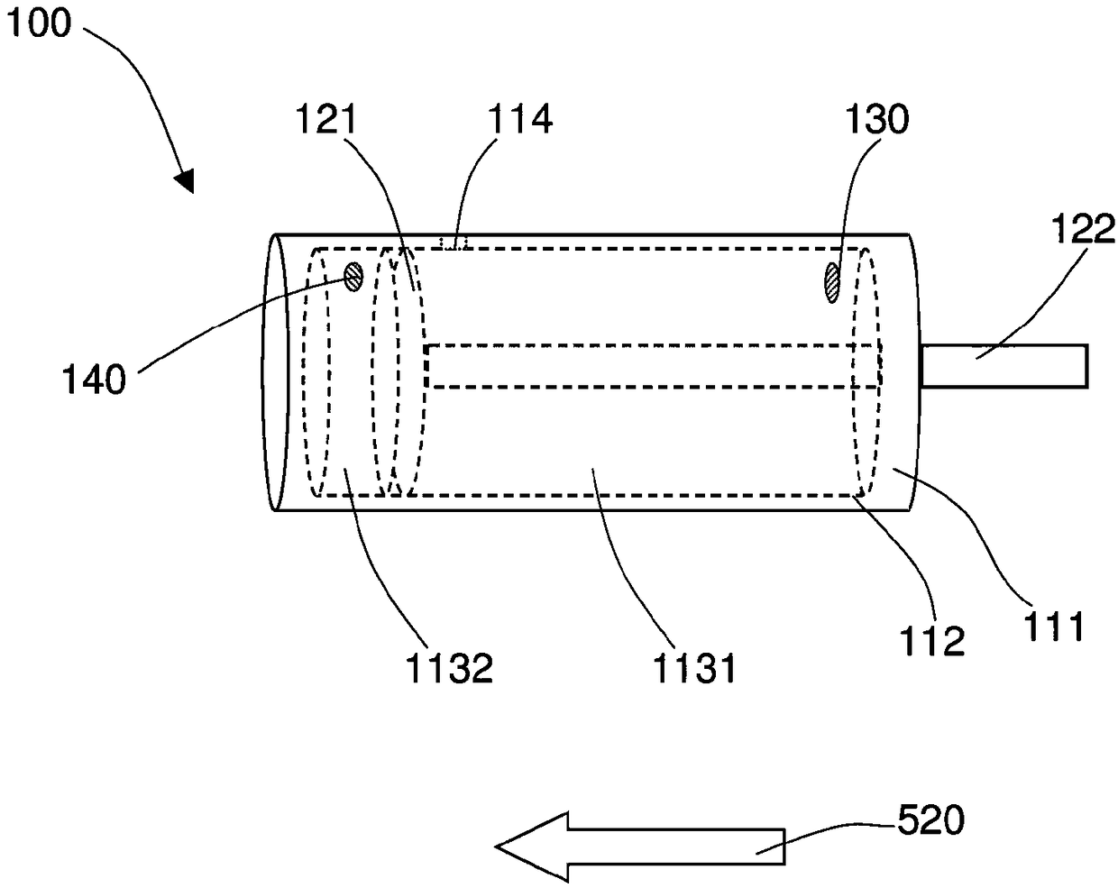
[0062] figure 1Shown is a schematic structural diagram of a sensor 100 according to an embodiment of the present invention. In the figure, the sensor 100 includes an air valve 110, a first sounding device 130 and a second sounding device 140 respectively arranged at both ends of the air valve 110, and a piston 120 slidably installed inside the air valve 110. The air valve 110 includes a housing 111 and a cavity 112 formed in the casing 111, the casing 111 is roughly in the shape of a hollow cylinder, the inner side wall of the cavity 112 is roughly a smooth arc surface, and the surface of the casing 111 is provided with a vent hole 114 connected to the cavity 112; The piston 120 includes a plug body 121 and a push rod 122 extending from one side of the plug body 121 , the plug body 120 is slidably connected to the inner wall of the cavity 112 to form an air chamber 113 , and divides the air chamber 113 into a first air chamber 1131 and the second air chamber 1132, the push ro...


PUM


Abstract

A sensor is used for judging the position state of a first tested object and a second tested object adjacent to each other and comprises an air valve which is arranged on the first tested object, wherein the air valve comprises a shell and a cavity formed in the shell; a first sound production device which is fixedly arranged at one end of the shell and is communicated with the cavity; a second sound production device which is fixedly arranged at the other end of the shell and is communicated with the cavity; and a piston which is connected with the second tested object and the air valve, wherein the piston comprises a plug body and a push rod extending out from one side of the plug body, the plug body is slidably connected to the inner side wall of the cavity to form an air chamber, and the tail end of the push rod is connected with the second tested object. A monitoring system comprises a monitoring module and the sensor installed on the second tested object, and is used for monitoring the position state of the first tested object and the second tested object adjacent to each other. The sensor does not generate noise during working, and does not need a power supply. Wire arranging and replacement of a battery are avoided, and the installation and maintenance are convenient.

Description

technical field [0001] The invention relates to the technical field of sensor monitoring, in particular to a sensor and a monitoring system using the sensor. Background technique [0002] With the continuous improvement of people's awareness of security and anti-theft, more and more people choose to install sensors on the doors or windows of their homes, and install matching monitoring systems to monitor and protect their property. When the door or window is opened maliciously, the sensor perceives the opening and closing status of the door or window and sends an alarm to the user through the security monitoring system, reminding the user to deal with it in time, so as to reduce the property loss of the user. [0003] Most of the existing sensors are powered by electricity. Generally, they use cables to connect to the power supply or use batteries. When using cables to connect to the power supply, it is necessary to plan the wiring when building the house. If the wiring of t...

Claims


Application Information

Patent Timeline
Patent Type & Authority Applications(China)
IPC IPC(8): G08B13/08G08B13/16
CPCG08B13/08G08B13/1681
Inventor 林益全鄢玉虎
Owner AMBIT MICROSYSTEMS (SHANGHAI) LTD
Learn More