Device for guiding electric tool operating direction

a technology of operating direction and electric tools, which is applied in the direction of manufacturing tools, metal sawing accessories, large fixed members, etc., can solve the problems of endangering the circuit of the machine, wasting unfinished product materials, and inconvenience caused by battery replacemen

Inactive Publication Date: 2006-07-20
PU JIAN HUA
View PDF5 Cites 15 Cited by
  • Summary
  • Abstract
  • Description
  • Claims
  • Application Information

AI Technical Summary

Benefits of technology

[0008] A primary objective of the present invention is to resolve the aforementioned shortcomings. The present invention uses electromagnetic induction to provide a power supply to a guide, thereby eliminating the need to replace batteries to supply power to the guide, and is characterized in that even if an electric tool machine stops working during machining, a guide indicator can be still produced as a reference guide for machining.
[0009] In order to achieve the aforementioned objective, a device for guiding electric tool operating direction of the present invention utilizes two coils, wherein when alternating voltage is applied to the first coil, an alternating voltage output is induced in the second coil. Value of the alternating voltage output depends on ratio of windings on the two coils. The first coil is fixed coil, and the second coil coaxially rotates along with a cutting tool. The induced alternating voltage output of the second coil is supplied to an electronic circuit, which after processing provides power to activate the guide, which then emits a laser light for guiding operating direction. Hence, the need to replace batteries to supply power to the guide is eliminated, and, moreover, function to guide alignment direction for electric tool finishing is achieved.

Problems solved by technology

However, during course of cutting or drilling holes using the aforementioned machining method, the worker is generally unable to clearly see the previously drawn lines or marks, which easily results in the worker wrongly cutting or wrongly drilling the unfinished product, and thus causing wastage in unfinished product material.
However, because the two aforementioned cited patents use batteries as a power supply, thus inconvenience is caused when replacing the batteries.
However, because of variation in rotating speed of the cutting tool, thus current is unstable, which thereby further results in endangering circuits in the machine.
Moreover, when the machine stops working, because of inability to generate power, thus ability to produce the indicator light is also lost.

Method used


Image

  • Device for guiding electric tool operating direction
  • Device for guiding electric tool operating direction
  • Device for guiding electric tool operating direction

Examples


first embodiment

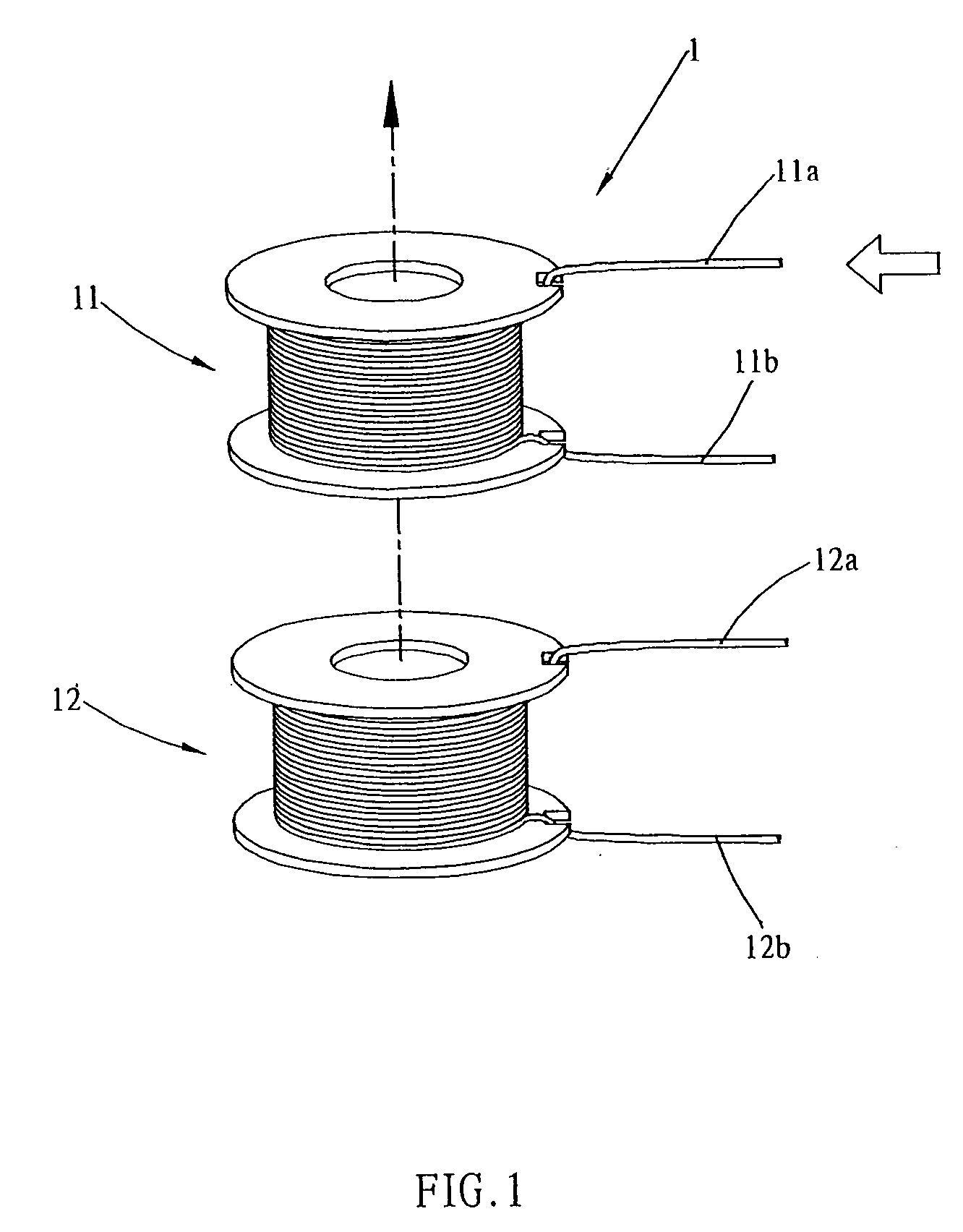
[0020] Referring to FIG. 1, which shows a schematic view of a first embodiment according to the present invention, wherein a device for guiding electric tool operating direction primarily comprises a power supply unit 1 that uses an electromagnetic induction method to transmit power, thereby enabling a guide (not shown in FIG. 1), which follows movement of a cutting tool (not shown in FIG. 1), to produce a machining line to guide operating direction of the cutting tool, thus enabling an operator to align cutting with the machining line on an unfinished product.

[0021] The aforementioned power supply unit 1 is structured to include a first coil 11 and a second coil 12, which together form an inductor. When alternating voltage is applied to input terminals 11a and 11b of the first coil 11, thus another alternating voltage is induced in the second coil 12 through electromagnetic induction of the inductor, which is output from output terminals 12a and 12b of the second coil 12. Value of ...

second embodiment

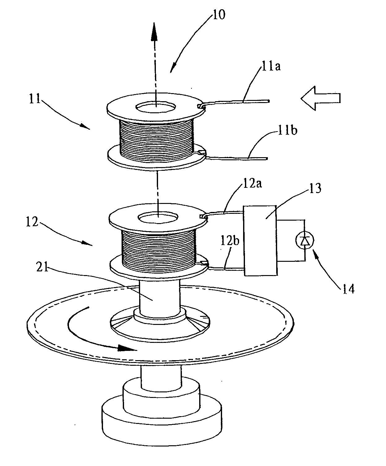
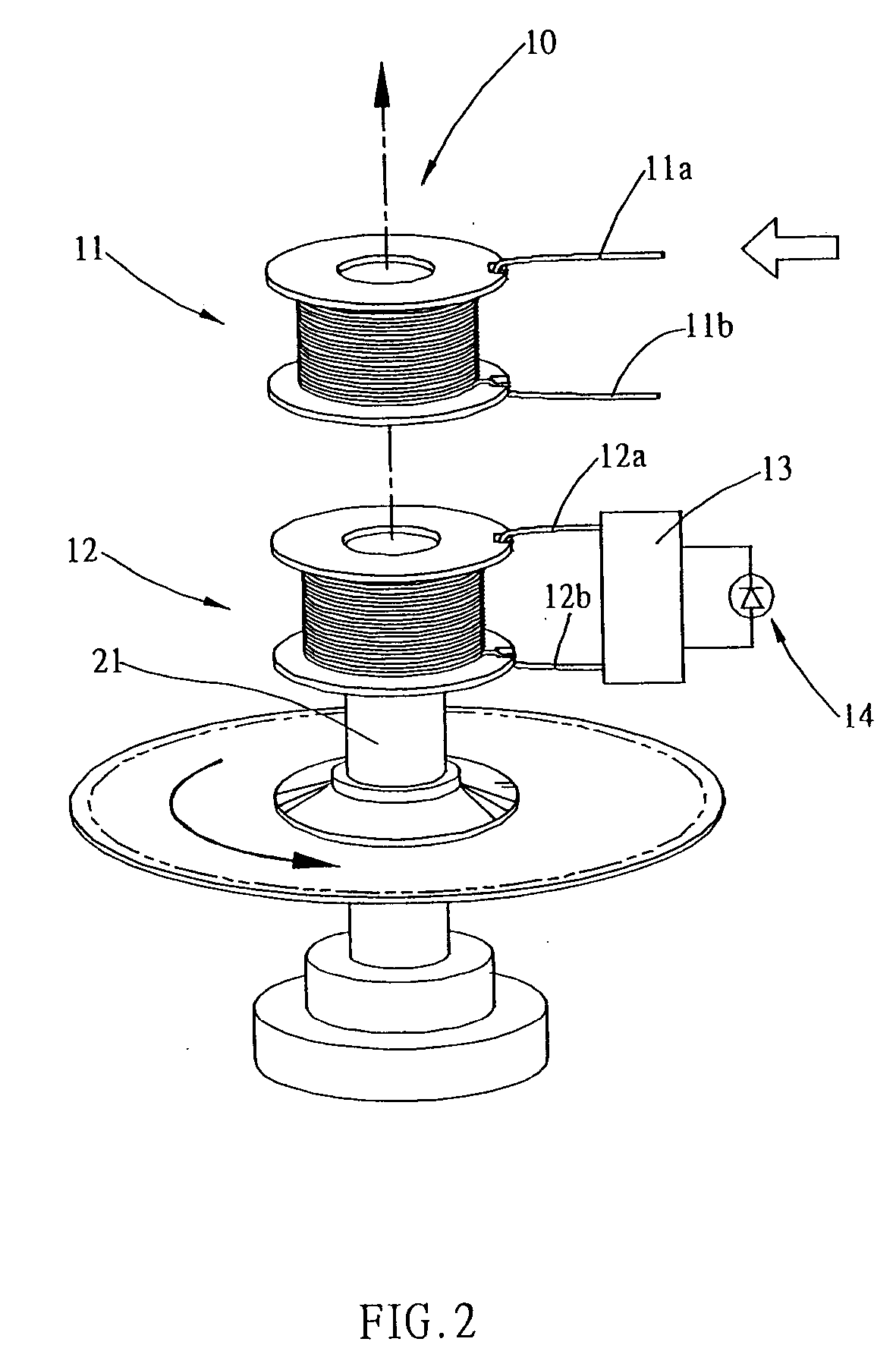
[0022] Referring to FIG. 2, which shows a schematic view of the present invention, wherein axis of symmetry of the first coil 11 and the second coil 12 is along an identical straight line, and the first coil 11 is fixed. The second coil 12, which rotates round a rotating shaft 10, is connected to a cutting tool. Alternating voltage applied to the input terminals 11a and 11b of the fixed first coil 11 induces alternating voltage in the second coil 12, which is output from the output terminals 12a and 12b of the second coil 12 of the rotating shaft 10. The output terminals 12a and 12b of the second coil 12 are connected to an electronic circuit 13, which encompasses either a rectifier or a stabilizer, and a drive circuit, and can commutate or stabilize the alternating voltage output from the output terminals 12a and 12b of the second coil 12, thereby providing at least one guide 14 with a power supply. After the guide 14 has been activated, laser light produced therefrom emits intermi...

third embodiment

[0023] Referring to FIG. 3, which shows a schematic view of the present invention, wherein a center tapped output terminal 12c extends from a center of the second coil 12. The output terminal 12c connects to the electronic circuit 13 of the guide 14, and transmits a pulsating direct current towards the guide 14, and as long as the rotating speed is fast enough, then there will be no variation in brightness of the light seen by the human eye.

[0024] Referring to FIG. 4a and 4b, wherein FIG. 4a shows a cutaway view of a first example of usage of the present invention, wherein the aforementioned guide 14 is utilized to ascertain the operating direction of the tool, for instance, usage on an electric circular saw, wherein a circular saw blade 101 and a laser box 102 are appositionally affixed to the rotating shaft 10 of the circular saw. FIG. 4b shows an internal view of the laser box 102 as seen along direction of the rotating shaft 10. The second coil 12 is disposed so as to encircle t...


PUM

PropertyMeasurementUnit
voltageaaaaaaaaaa
voltageaaaaaaaaaa
alternating voltageaaaaaaaaaa

Abstract

A device for guiding electric tool operating direction, which is disposed on an electric tool, and includes: a power supply unit structured from two mutually configured coaxial coils, wherein one of the coils is a fixed coil, and a second coil is attached to a rotating end, alternating voltage is applied to the fixed coil, which induces alternating voltage output in the second coil through electromagnetic induction, thereby providing power to activate a guide to produce an indicator light. Even if an electric tool machine stops working during machining, the guiding indicator light can be still produced as a reference guide for machining.

Description

BACKGROUND OF THE INVENTION [0001] (a) Field of the Invention [0002] The present invention relates to a device for guiding electric tool operating direction, and more particularly to a device that uses an electromagnetic induction method to produce a power supply for a guide, which is thereby enabled to guide alignment direction for electric tool finishing. Even if an electric tool machine stops working during machining, an optical guide indicator can be still produced as a reference guide for machining. [0003] (b) Description of the Prior Art [0004] Currently, when manufacturing products (furniture, steel windows, and so on) or when decorating, an electric tool is used to cut or drill holes in an unfinished product. When the unfinished product is to be cut or holes drilled therein, a worker first uses a pen or chalk line to draw lines or marks on the unfinished product, and the worker then uses the electric tool to cut or drill holes in the unfinished product using the previously d...

Claims


Application Information

Patent Timeline
Patent Type & Authority Applications(United States)
IPC IPC(8): B23B49/00B23G1/00
CPCB23Q1/0009B25H1/0092Y10T408/98Y10T408/21B23D59/003
Inventor PU, JIAN-HUA
Owner PU JIAN HUA
Why Eureka
Try Eureka