Sample loading device
A technology for loading samples and samples, which is applied in the field of sample loading devices, can solve the problems of unsatisfactory requirements, inconvenient sample loading, and sample drop, etc., and achieve the effect of fast sample loading, not easy to drop samples, and large sample loading space
- Summary
- Abstract
- Description
- Claims
- Application Information
AI Technical Summary
Problems solved by technology
Method used
Image
Examples
Embodiment 1
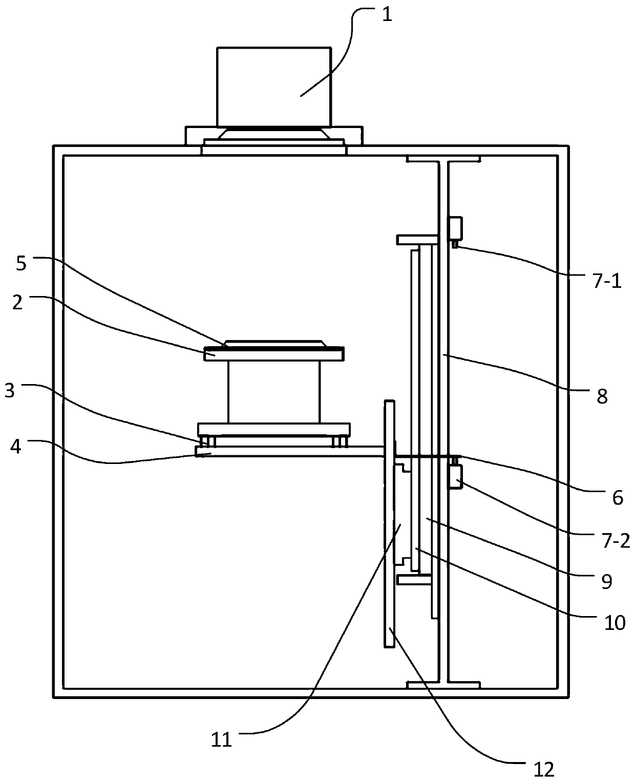
[0041] Such as figure 1 As shown, the present embodiment provides a sample loading device, including a box, the interior of the box is provided with a column 8, the height of the column 8 can be set according to the needs of the experiment, preferably, the column 8 The top end of the column 8 is fixedly connected with the top wall of the box body, and the bottom end of the column 8 is fixedly connected with the bottom wall of the box body. The top wall of the box body is provided with an opening, the top of the opening is provided with a first chamber 1, and the first chamber 1 is fixed on the outer wall of the top wall of the box body, and the first chamber The chamber 1 is a cavity with an open end and a certain space inside, and the opening of the first chamber 1 faces downward.
[0042] The sample loading device also includes a sample stage 2 arranged inside the box, the sample stage 2 is located directly below the first chamber 1, when the sample stage 2 and the first ch...
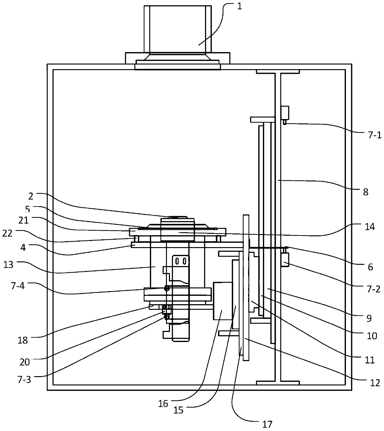
Embodiment 2
[0051] Such as figure 2 As shown, this embodiment provides a sample loading device with a more convenient, faster and safer sample loading process. A sample loading device, comprising a box, the inside of the box is provided with a column 8, the top of the column 8 is fixedly connected to the top wall of the box, and the bottom of the column 8 is connected to the box body The bottom wall is fixedly connected. The top wall of the box body is provided with an opening, the top of the opening is provided with a first chamber 1, and the first chamber 1 is fixed on the outer wall of the top wall of the box body, and the first chamber The chamber 1 is a cavity with an open end and a certain space inside, and the opening of the first chamber 1 faces downward. The sample loading device also includes a fastening plate 21 arranged inside the box, the fastening plate 21 is located directly below the first chamber 1, when the fastening plate 21 and the first chamber 1 When fastened tog...
Embodiment 3
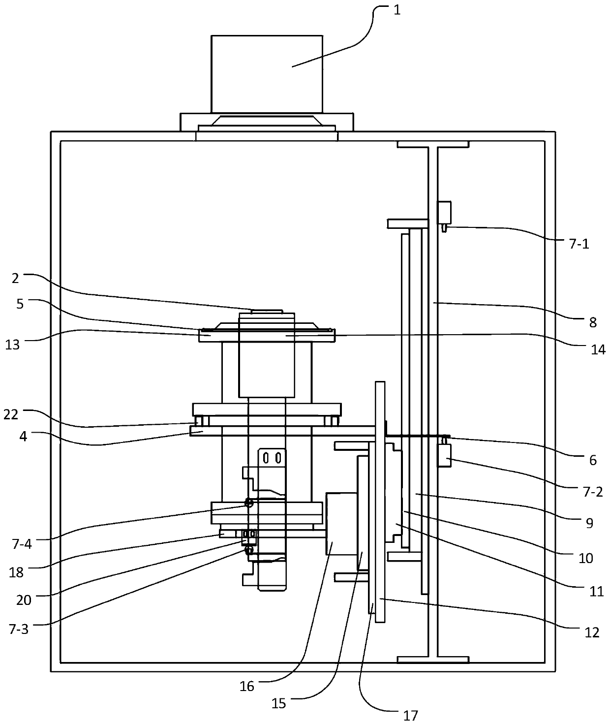
[0062] The structure of this embodiment is basically the same as that of Embodiment 2. The difference between this embodiment and Embodiment 2 is that the second chamber 13 in this embodiment, such as image 3 As shown, the fastening plate 21 in the second embodiment is replaced. The lower end of the second chamber 13 is connected to the second sealing member 22. Preferably, the second sealing member 22 is a welded bellows. A through hole is respectively arranged on the upper end surface and the lower end surface of the second sealing member 22. The lifting rod 14 The through hole passing through the upper end surface of the welded bellows passes through the second chamber 13 . Further, the second chamber 13 is connected with vacuum equipment (not shown in the figure), when testing in the first chamber 13 or producing products that require a high vacuum degree, the first chamber 1 and the first chamber are simultaneously The second chamber 13 is evacuated to increase the degr...
PUM
 Abstract
Description
Claims
Application Information
 - R&D Engineer
- R&D Manager
- IP Professional
- Industry Leading Data Capabilities
- Powerful AI technology
- Patent DNA Extraction
Browse by: Latest US Patents, China's latest patents, Technical Efficacy Thesaurus, Application Domain, Technology Topic, Popular Technical Reports.
© 2024 PatSnap. All rights reserved.Legal|Privacy policy|Modern Slavery Act Transparency Statement|Sitemap|About US| Contact US: help@patsnap.com


