Double-seal high-pressure polished rod sealing device

A polished rod sealer and double-seal technology, which is applied in sealing/packing, wellbore/well parts, earthwork drilling and production, etc., can solve the problem of uneven force on the sealing ring, shortening the service life of the sealing ring, and poor sealing of the polished rod, etc. problem, to achieve good sealing effect and improve the sealing effect

Inactive Publication Date: 2018-10-19
FUNING COUNTY PETROL MECHANICAL LIMITED
View PDF0 Cites 4 Cited by
  • Summary
  • Abstract
  • Description
  • Claims
  • Application Information

AI Technical Summary

Problems solved by technology

However, due to the influence of various factors such as downhole working conditions, manufacturing precision of the oil pumping equipment, and deformation of parts of the oil pumping equipment after bearing loads, the axis of the polished rod and the axis of the polished rod sealer are likely to deviate. During the reciprocating movement of the polished rod up and down, it will be accompanied by a horizontal displacement in a certain direction, which will cause uneven force on the contact surface between the sealing ring and the polished rod, and the side of the sealing ring that is stressed will wear faster, reducing the The service life of the sealing ring leads to the poor sealing of the polished rod. Therefore, we propose a double-seal high-pressure polished rod sealer

Method used


Image

  • Double-seal high-pressure polished rod sealing device
  • Double-seal high-pressure polished rod sealing device

Examples


Embodiment Construction

[0014] The following will clearly and completely describe the technical solutions in the embodiments of the present invention with reference to the accompanying drawings in the embodiments of the present invention. Obviously, the described embodiments are only some, not all, embodiments of the present invention. Based on the embodiments of the present invention, all other embodiments obtained by persons of ordinary skill in the art without making creative efforts belong to the protection scope of the present invention.

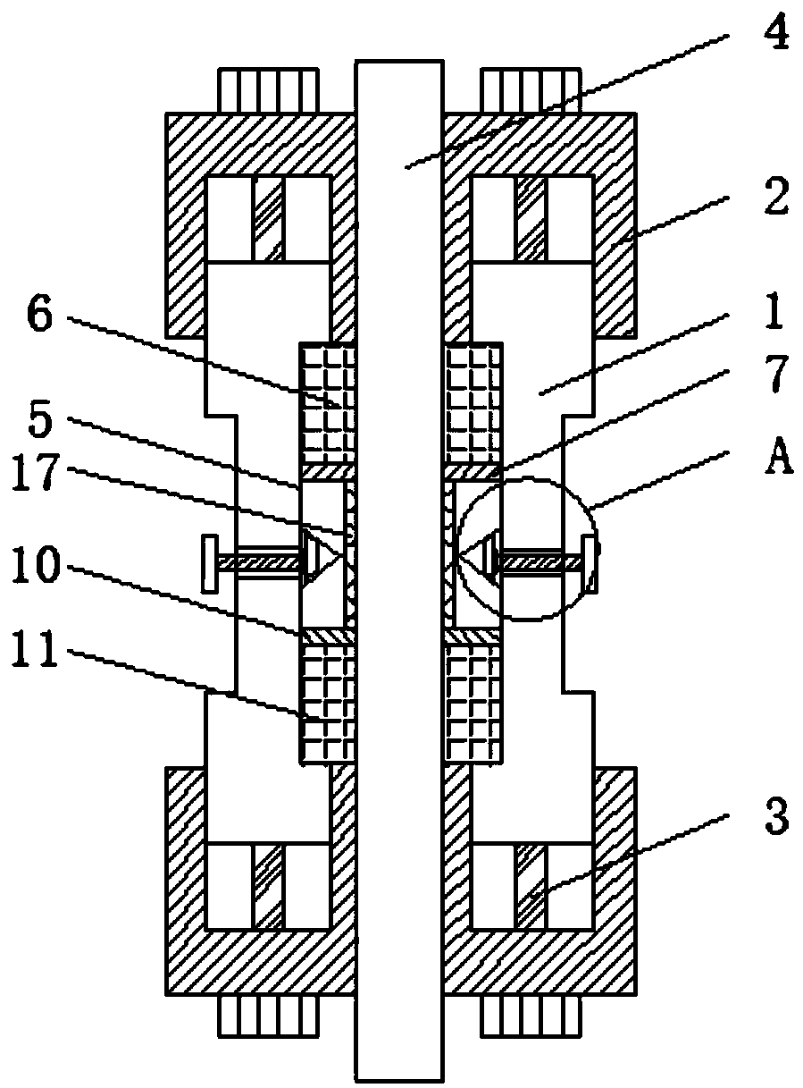
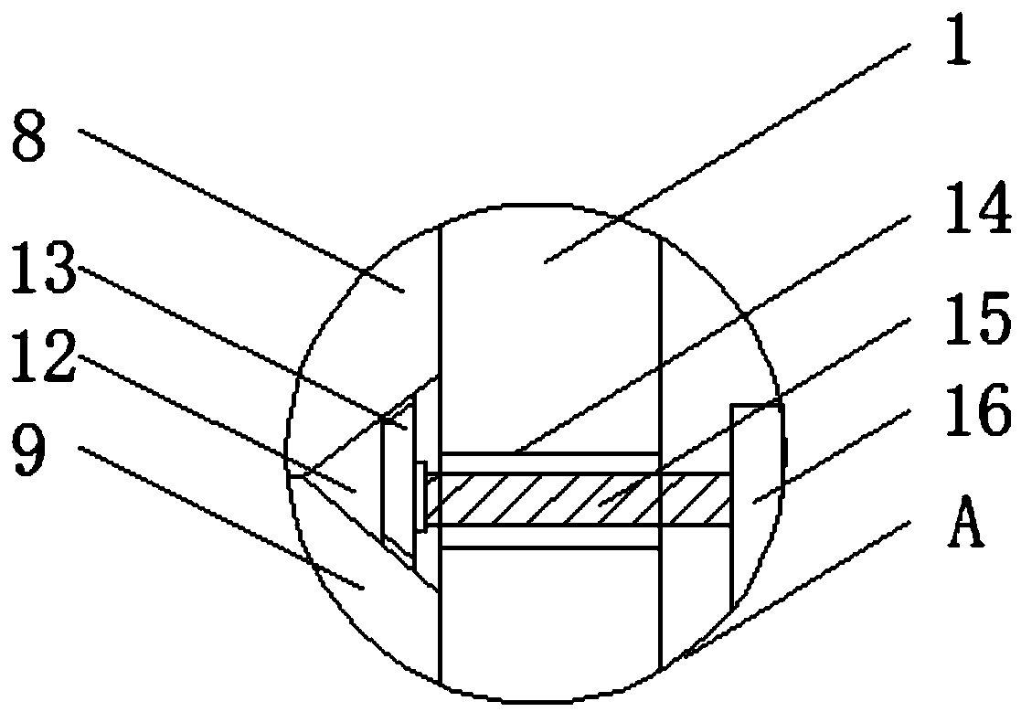
[0015] see Figure 1-2 , the present invention provides a technical solution: a double-seal high-pressure polished rod sealer, including a sealed casing 1, the top and bottom of the sealed casing 1 are installed with a pressure cap 2 through bolts 3, the sealed casing 1 is provided with a polished rod 4, and the sealed casing 1 1 There is a groove 5 on the side close to the polished rod 4, and the upper sealing ring 6, the upper backing ring 7, the upper movin...


PUM

PropertyMeasurementUnit
Slope angleaaaaaaaaaa

Abstract

The invention discloses a double-seal high-pressure polished rod sealing device, and belongs to the technical field of polished rod sealing devices. The double-seal high-pressure polished rod sealingdevice comprises a sealing shell. A groove is formed in the side, which is close to a polished rod, of the sealing shell, an upper sealing ring, an upper spacer, an upper movable block, a lower movable block, a lower spacer and a lower sealing ring are sequentially mounted in the groove from top to bottom, mounting balls are mounted on the side, which is close to the polished rod, of each of the upper movable block and the lower movable block, oblique planes are arranged on the adjacent surfaces of the upper movable block and the lower movable block, a triangular notch is formed between the upper movable block and the lower movable block, an ejecting block is slidably arranged in the triangular notch, a threaded hole is formed in the sealing shell, and a threaded rod is mounted in the threaded hole. The double-seal high-pressure polished rod sealing device has the advantages that the upper movable block and the lower movable block can move towards two sides of the double-seal high-pressure polished rod sealing device, accordingly, the upper sealing ring and the lower sealing ring can be squeezed, can be expanded towards the horizontal directions and can sufficiently cling to the outer wall of the polished rod, accordingly, the sealing purpose can be achieved, and sealing effects can be improved.

Description

technical field [0001] The invention relates to the technical field of polished rod sealers, in particular to a double-seal high-pressure polished rod sealer. Background technique [0002] In the process of oil extraction, the oil pumping equipment on the ground drives the downhole oil pump to work through the polished rod and sucker rod to pump the downhole crude oil to the ground. During the oil pumping process, the polished rod continuously reciprocates up and down at the wellhead, In order to keep the sealing of the annular space between the polished rod and the tubing and prevent crude oil from seeping out, a polished rod sealer is usually installed at the wellhead. However, due to the influence of various factors such as downhole working conditions, manufacturing precision of the oil pumping equipment, and deformation of parts of the oil pumping equipment after bearing loads, the axis of the polished rod and the axis of the polished rod sealer are likely to deviate. D...

Claims


Application Information

Patent Timeline
IPC IPC(8): E21B33/03
CPCE21B33/03
Inventor 周正军魏高华
Owner FUNING COUNTY PETROL MECHANICAL LIMITED
Why Eureka
Try Eureka