Changeover valve

A technology of vacuum cleaner and switching valve, which is applied in the field of switching valve to achieve the effect of reducing wear and improving sealing

Inactive Publication Date: 2003-12-10
DYSON TECH LTD
View PDF3 Cites 0 Cited by
  • Summary
  • Abstract
  • Description
  • Claims
  • Application Information

AI Technical Summary

Problems solved by technology

Another object is to provide a changeover valve which can be easily and quickly accessed internally and serviced should any maintenance be required

Method used


Image

  • Changeover valve
  • Changeover valve
  • Changeover valve

Examples


Embodiment Construction

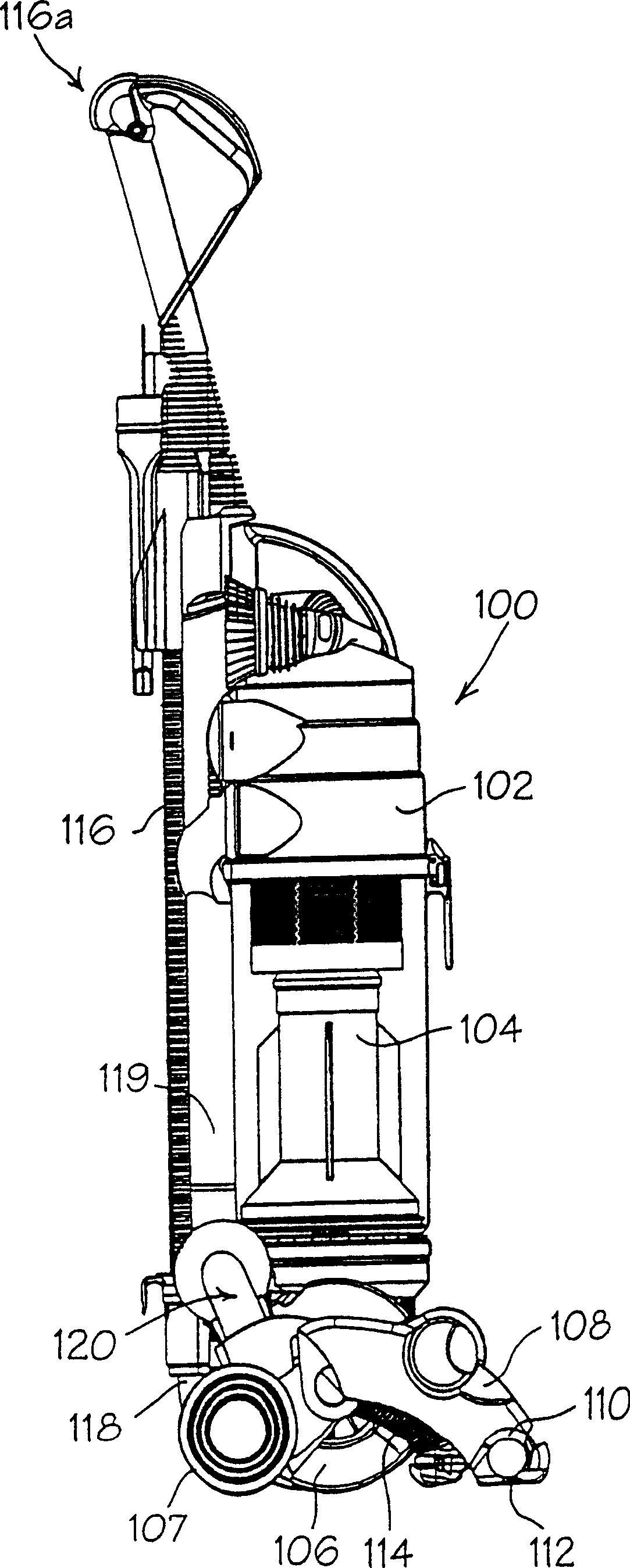
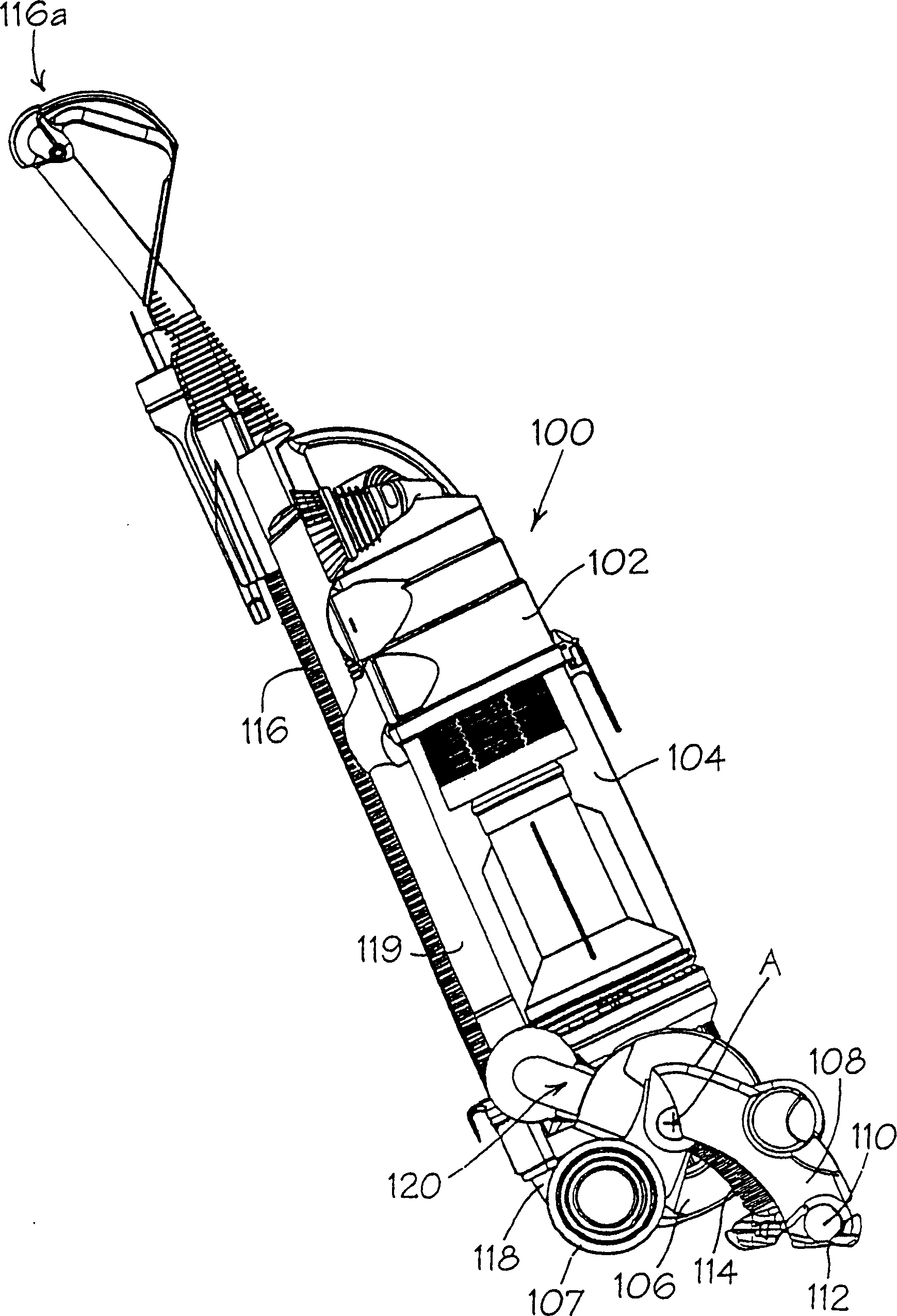
[0020] figure 1 and 2 The entire structure of an upright vacuum cleaner equipped with a switching valve according to the present invention is illustrated. The vacuum cleaner 100 has a main body 102 in which a dust separation mechanism 104 is mounted. In this embodiment the dust separation mechanism 104 is a cyclone dust separation mechanism consisting of two cyclones connected in series. Mechanisms of this type are well known and will not be described any further here, as they have no substantial effect on the invention. The motor housing 106 is located at the lower end of the main body 102 and constitutes a part of the main body 102 . The support wheel 107 is mounted directly on the motor housing 106 . The cleaner head 108 is rotatably mounted on the motor housing 106 about the axis A. As shown in FIG. The cleaner head 108 has a brush housing 110 with an inlet 112 arranged downwards at the front end of the cleaner head 108 . A switch valve 120 is located on the body 102...


PUM


Abstract

A changeover valve (100) comprises a first valve member (20) and a second valve member (50). The first valve member (20) has an aperture (28). The second valve member (50) has first and second apertures (54, 58). The first valve member (20) is movable relative to the second valve member (50) for selective alignment of the first valve member aperture (28) with one or other of the apertures (54, 58) of the second valve member (50). The valve (100) also has a ramp and follower means (29, 62) for automatically moving the valve members (20, 50) away from the one another during changeover movement of the first valve member (20) relative to the second valve member (50) so that wear on the surfaces of the valve members (20, 50) is minimised.

Description

technical field [0001] The present invention relates to a diverter valve, in particular, but not exclusively, to a diverter valve for a vacuum cleaner. Background technique [0002] Upright vacuum cleaners generally have a cleaner head rotatably mounted on the lower end of the main body, and a dust separation mechanism is installed in the head. The dust separation mechanism may be in the form of a conventional bag filter or a cyclone separator consisting of one or two cyclones, as described and shown in European patent EP 0042723. Position the propel cleaner across the handle of the floor to be cleaned, extending upward from or behind the main body. A pair of supporting wheels is mounted on the lower end of the main body or on the head of the vacuum cleaner. The cleaner head extends forward. The dirty air inlet is located at the front of the cleaner head and faces downwards so that in use the dirty air inlet faces the surface to be cleaned. A motor-driven fan draws dirty...

Claims


Application Information

Patent Timeline
IPC IPC(8): A47L9/24A47L5/30A47L5/32F16K5/18F16K11/076F16K31/58
CPCF16K11/076F16K5/184Y10T137/87804F16K31/58A47L5/32
Inventor A·W·M·汤姆森P·D·加马克R·B·西曼
Owner DYSON TECH LTD
Why Eureka
Try Eureka