Fixing device and intelligent ophthalmoscope using fixing device

A technology for fixing devices and fixing components, which is applied in the field of smart ophthalmoscopes, and can solve the problems of large ophthalmic examination equipment, long ophthalmologist training period of ophthalmic medical resources, and blindness.

Active Publication Date: 2018-10-19
PEKING UNION MEDICAL COLLEGE HOSPITAL CHINESE ACAD OF MEDICAL SCI
View PDF5 Cites 0 Cited by
  • Summary
  • Abstract
  • Description
  • Claims
  • Application Information

AI Technical Summary

Problems solved by technology

Residents in poor, remote and economically underdeveloped areas have a high rate of missed and misdiagnosed eye diseases, resulting in many patients losing the best opportunity for treatment, resulting in significant loss of vision or even blindness, seriously affecting people's quality of life
The uneven distribution of ophthalmology medical resources is mainly due to the long trai

Method used


Image

  • Fixing device and intelligent ophthalmoscope using fixing device
  • Fixing device and intelligent ophthalmoscope using fixing device
  • Fixing device and intelligent ophthalmoscope using fixing device

Examples


Embodiment 1

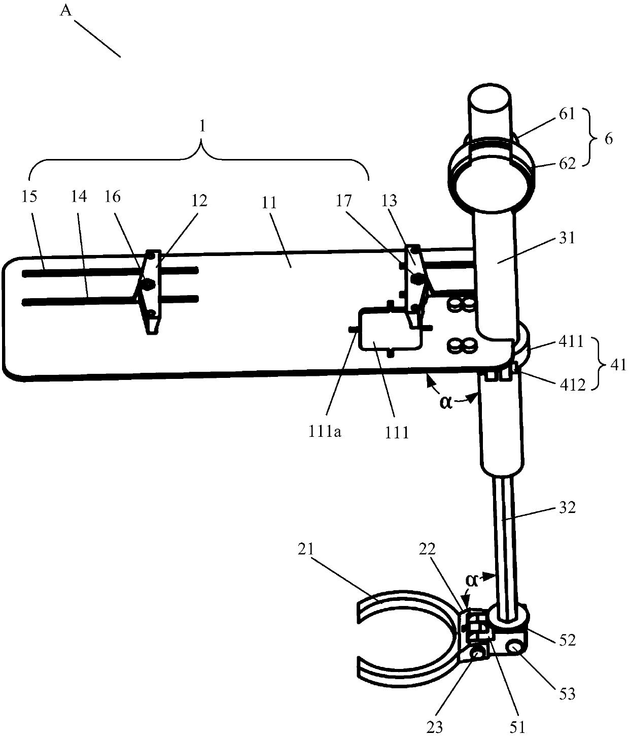
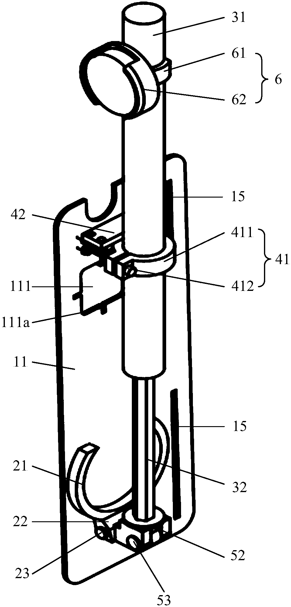
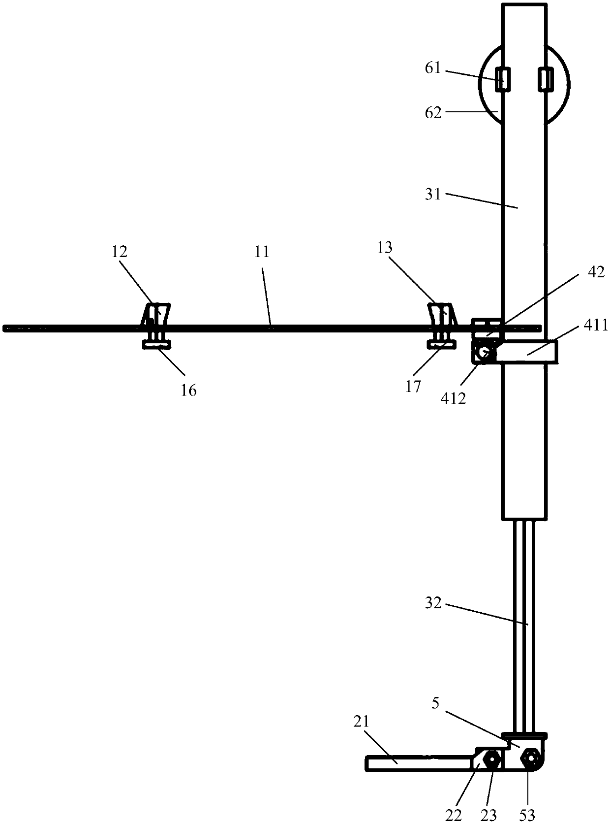
[0099] Figure 1-Figure 3 It is a schematic diagram of the fixing device of the embodiment of the present application. Such as Figure 1-Figure 3 As shown, the fixing device A includes a first fixing part 1 , a second fixing part 2 , a main body part 3 , a first connecting part 4 , a second connecting part 5 and a third connecting part 6 . The first fixing part 1 is rotatably connected to the main body part 3 through the first connecting part 4 . The second fixing part 2 is rotatably connected with the main body part 3 through the second connecting part 5 . Wherein, the relative distance between the first fixing part 1 and the second fixing part 2 is adjustable. The first fixing part 1 is used to fix the mobile terminal B (not shown in the figure), and the second fixing part 2 is used to fix the optical lens C (not shown in the figure), thereby forming a simple portable smart ophthalmoscope. The first fixing part 1 and the second fixing part 2 are configured in a folded st...

Embodiment 2

[0120] Figure 11 and Figure 12 It is a structural schematic diagram of the fixing device of the embodiment of the present application. Such as Figure 11-Figure 12 As shown, the structure of the fixing device of the present application is basically the same as that of the fixing device in the first embodiment, the only difference is that the structure of the first fixing part 1 is different from that of the first fixing part 1 in the first embodiment. details as follows:

[0121] The first fixing part 1 includes a support plate 11 , a first sliding part 12 , a second sliding part 13 , a first group of fixing blocks 18 , a second group of fixing blocks 19 , a first guide rail 110 and a second guide rail 120 . Both the first group of fixing blocks 18 and the second group of fixing blocks 19 include two parallel fixing blocks, which are respectively fixedly connected with the support plate 11 and arranged at the bottom of the support plate 11 . Each fixing block is provided...

Embodiment 3

[0126] This embodiment provides a smart ophthalmoscope, including a fixing device A, a mobile terminal B (not shown in the figure), and an optical lens C (not shown in the figure). The structure of the fixing device A is the same as that described in Embodiment 1 and Embodiment 2. The mobile terminal B includes a mobile phone, a camera, a tablet computer, and the like. The mobile terminal B includes a camera and a light emitting unit, which are clamped and fixed on the support plate 11 by the first sliding part 12 and the second sliding part 13 . The camera and the light emitting unit of the mobile terminal B are exposed through the observation window 111 to capture eye images. The optical lens C is fixed on the clamping portion 21 of the second fixing member 2 . In this embodiment, the distance between the mobile terminal B and the optical lens C is adjusted through the extension and contraction of the main body 3 . At the same time, the mobile terminal B and the optical l...


PUM

PropertyMeasurementUnit
Telescopic lengthaaaaaaaaaa

Abstract

The invention discloses a fixing device and an intelligent ophthalmoscope using the fixing device. The intelligent ophthalmoscope comprises a mobile terminal, an optical lens and the fixing device, wherein the fixing device comprises a first fixing component and a second fixing component; the relative distance of the first fixing component and the second fixing component is adjustable; the first fixing component is used for fixing the mobile terminal; the second fixing component is used for fixing the optical lens; and in an unfolded state, the center of a camera of the mobile terminal is coaxial with the center of the optical lens. Through the fixing device, the distance between the mobile terminal and the optical lens can be precisely regulated; eye images of different patients can be fast and conveniently collected; the collected images can be transmitted and stored through the mobile Internet; and the remote consultation is realized.

Description

technical field [0001] The present application relates to the field of medical examination equipment, in particular to a fixing device and an intelligent ophthalmoscope using the same. Background technique [0002] With the aging of the Chinese population and changes in lifestyles, diabetes and hypertension have led to rapid increases in fundus diseases and other related diseases. At present, the distribution of ophthalmic medical resources in my country and other developing countries is uneven. Residents in poor, remote and economically underdeveloped areas have a high rate of missed and misdiagnosed eye diseases, resulting in many patients losing the best opportunity for treatment, resulting in significant loss of vision or even blindness, seriously affecting people's quality of life. The uneven distribution of ophthalmology medical resources is mainly due to the long training period and small number of ophthalmologists, who are concentrated in large cities or economicall...

Claims


Application Information

Patent Timeline
IPC IPC(8): F16M11/04A61B3/12
CPCA61B3/12F16M11/041
Inventor 吴婵戴荣平陈有信杜旭联
Owner PEKING UNION MEDICAL COLLEGE HOSPITAL CHINESE ACAD OF MEDICAL SCI
Why Eureka
Try Eureka