
Manufacturing method and device of optical fiber intelligent carbon fiber sensor belt

An optical fiber intelligence and a technology for making devices, which are applied in measurement devices, measurement and instruments by measuring the changing force of optical properties of materials when they are stressed, can solve the problems of lack of path planning and low accuracy of optical fiber paths, and reduce the Complexity, good extraction effect, uniform prestress effect

Active Publication Date: 2020-11-03
GUANGZHOU UNIVERSITY
View PDF2 Cites 0 Cited by
  • Summary
  • Abstract
  • Description
  • Claims
  • Application Information

AI Technical Summary

Problems solved by technology

[0006] The purpose of the present invention is to solve the problem that the optical fiber implantation method in the above prior art has no path planning and the accuracy of manual recording of the optical fiber path is low, and proposes a method and device for making an optical fiber smart carbon fiber sensor belt, which can perform optical fiber path Effective planning and documentation

Method used


Image

  • Manufacturing method and device of optical fiber intelligent carbon fiber sensor belt
  • Manufacturing method and device of optical fiber intelligent carbon fiber sensor belt
  • Manufacturing method and device of optical fiber intelligent carbon fiber sensor belt

Examples


Embodiment 1

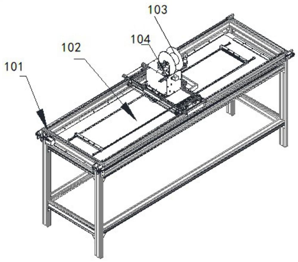
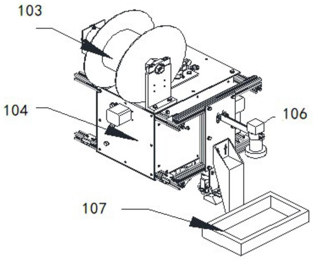
[0054] refer to Figure 1-Figure 3, the present embodiment provides a manufacturing device for an optical fiber smart carbon fiber sensor belt, including a frame 101, a workbench 102, an optical fiber drum 103, a laying head assembly 104, a servo device, an image acquisition device 106, and a processor;

[0055] The workbench 102 is fixed on the frame 101 for laying carbon fiber prepreg;

[0056] An optical fiber is wound on the optical fiber drum 103, and the servo device is used to drive the movement of the placement head assembly 104, so as to lay the optical fiber on the carbon fiber prepreg according to a preset path;

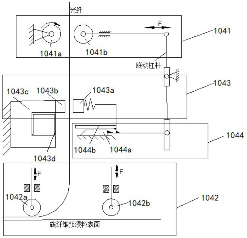
[0057] The placement head assembly includes a re-sending module 1041, a compacting module 1042, a clamping module 1043, and a shearing module 1044. The re-sending module 1041 is used to transport the optical fiber, and the compacting module 1042 is used to press the optical fiber to the carbon fiber prefab according to a preset path. On the dipping materi...

Embodiment 2

[0074] The present embodiment provides a kind of manufacture method of optical fiber smart carbon fiber sensing belt, refer to Figure 1-Figure 6 , using the manufacturing device of the optical fiber smart carbon fiber sensing belt provided in embodiment one to make, the method includes:

[0075] Step S101, fixing the carbon fiber prepreg on the workbench;

[0076] Step S102, transporting the optical fiber wound on the optical fiber drum to the carbon fiber prepreg through the re-feeding module;

[0077] Step S103, driving the laying head assembly to move along a preset path through the servo device;

[0078] Step S104, pressing the optical fiber onto the carbon fiber prepreg according to a preset path through the re-feeding module and the pressing module;

[0079] Step S105, after the optical fiber laying is completed, the clamping module clamps the optical fiber, and the cutting module cuts the optical fiber;

[0080] Step S106, the image acquisition device acquires the i...


PUM


Abstract

The invention provides a method and device for manufacturing an optical fiber intelligent carbon fiber sensor belt. The device includes a frame, a workbench, an optical fiber drum, a laying head assembly, a servo device, an image acquisition device, and a processor. The laying head assembly includes a heavy sending module, pressing module, clamping module and shearing module; the device and method can embed the optical fiber in the carbon fiber prepreg according to the preset path, and pass through the re-feeding module, pressing module, clamping module and shearing module With the cooperation of the optical fiber laying, the prestress is uniform, and the accuracy of finished product monitoring is improved. Machine vision is used instead of manual collection of optical fiber distribution maps, which is especially suitable for the production of large sensing belts.

Description

technical field [0001] The invention relates to a manufacturing method and device of an optical fiber intelligent carbon fiber sensing belt. Background technique [0002] Resin-based carbon fiber-reinforced composite materials have the advantages of high strength, low elastic modulus, and light weight, making carbon fiber materials more and more widely used in aircraft, wind energy blades and auto parts. Optical fiber has the advantages of wide bandwidth, low loss, shielding electromagnetic radiation, light weight, and good security and privacy. Its optical fiber sensing technology is suitable for high-voltage places, can transmit signals over long distances, is conducive to miniaturization, and is suitable for large-scale projects. Long-term security monitoring, etc. Therefore, optical fiber sensing technology has been highly valued and developed rapidly, and has become one of the key technologies that are urgently needed in many fields of the national economy such as majo...

Claims


Application Information

Patent Timeline
Patent Type & Authority Patents(China)
IPC IPC(8): G01L1/24
CPCG01L1/242
Inventor 朱萍玉谢啸博孙孝鹏吴江张佳南黄孟姣刘征
Owner GUANGZHOU UNIVERSITY
Learn More