
C-beam composite material forming tooling and composite material C-beam forming method

A composite material and molding tooling technology, used in household appliances, other household appliances, household components, etc., can solve the problems of internal and surface quality defects, thin forming R angle, etc., to achieve internal quality balance, pressure transmission uniform, contact tight effect

Active Publication Date: 2020-11-03
深圳市泰格尔航天航空科技有限公司
View PDF10 Cites 0 Cited by
  • Summary
  • Abstract
  • Description
  • Claims
  • Application Information

AI Technical Summary

Problems solved by technology

[0005] In order to overcome the deficiencies in the prior art, the present invention proposes a C-beam composite material forming tooling and a composite C-beam forming method. Problems with internal and surface quality defects

Method used


Image

  • C-beam composite material forming tooling and composite material C-beam forming method
  • C-beam composite material forming tooling and composite material C-beam forming method
  • C-beam composite material forming tooling and composite material C-beam forming method

Examples


Embodiment Construction

[0029] The following will be combined with Figures 1 to 5 The present invention is further described, but it should not be used to limit the protection scope of the present invention.

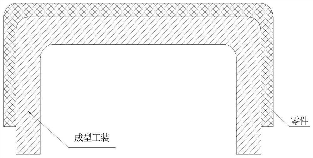
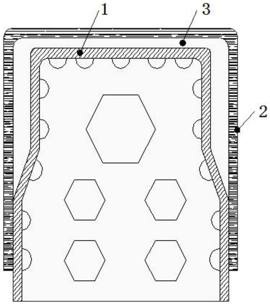
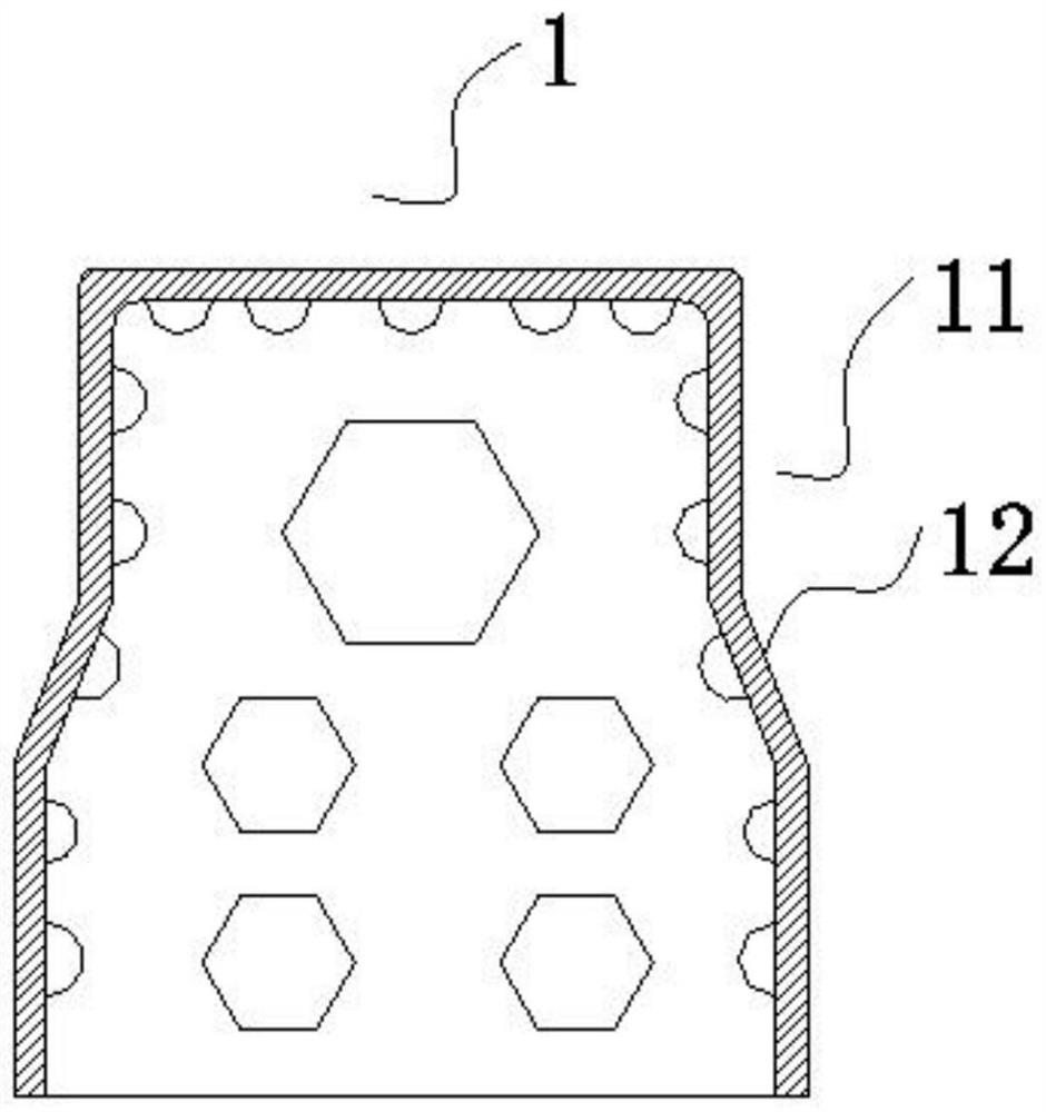
[0030] A C-shaped beam composite material forming tool is used to prepare a C-shaped beam including a web and two edges, and the forming tool includes a male mold part 1 and an auxiliary cover plate 2 .

[0031] Both sides of the male module 1 are inwardly recessed to form an indented area 11 whose thickness is consistent with the thickness of the two edges of the C-shaped beam; the upper end of each indented area 11 runs through the upper end surface of the male module 1, and At the lower end of the recessed area 11 is a boss structure 12 . The thickness of the boss structure 12 is the thickness of the workpiece to be manufactured. This technology can ensure that the quality and size of the R corner of the workpiece are uniform when curing the composite C-beam. Wherein, the boss structure ...


PUM


Abstract

The invention discloses a C-shaped beam composite material forming tool and a composite material C-shaped beam forming method. The forming tool comprises a male mould part and an auxiliary cover plate, wherein the two sides of the male mould part are inwards sunken to form sunken regions; the auxiliary cover plate covers the outer side of the male mould part; and the upper side end of the male mould part, the two inner sunken regions and the auxiliary cover plate define a cavity for placing a prepreg part. The forming method comprises the following steps of: coating a de-molding agent for composite material manufacturing on the male mould part; pre-soaking and automatically cutting according to a process expanded view; spreading prepreg on the male mould part in a layer-shaving and layingmode to form the prepreg part; placing a gas guide material on the outer side surface of the prepreg part; performing vacuum compaction treatment; covering the auxiliary cover plate at the peripheralside of the male mould part; and completing curing of a C-shaped beam through a vacuum bag pressing method. A manufactured C-shaped beam, an R angular ea, interior and surface quality, dimension precision and the like achieve the perfect requirements, and the auxiliary cover plate can be repeatedly utilized for many times, so that production efficiency is improved.

Description

technical field [0001] The invention relates to the technical field of composite material forming tooling and technology, in particular to a C-shaped beam composite material forming tool and a composite material C-shaped beam forming method. Background technique [0002] Carbon fiber composite materials used in aerospace have the advantages of high specific modulus, specific strength and designability, and have been widely used in my country's aerospace and national defense technology fields in recent years. Among the components in the aerospace field, there are many beam parts, which are used in the box section and other components to increase the overall strength and rigidity of the box section. [0003] Composite material "C" beam is a commonly used structural form of composite parts. The original conventional manufacturing process is ordinary male mold or female mold forming tooling. Due to the small size of the beam flange, the temperature and pressure of the flange bla...

Claims


Application Information

Patent Timeline
Patent Type & Authority Patents(China)
IPC IPC(8): B29C70/34B29C70/54B29L31/00
CPCB29C70/342B29C70/54B29L2031/001
Inventor 刘沛禹
Owner 深圳市泰格尔航天航空科技有限公司
Learn More