An electromagnetic locking device

A locking device, electromagnetic technology, applied to weapons without explosives, spring guns, offensive equipment, etc., can solve the problem that the locking device has no versatility, the locking device of the launching system is inconvenient to replace the locking device, and the launching system no issues of versatility

Active Publication Date: 2020-04-07
贵州振华群英电器有限公司(国营第八九一厂)
View PDF3 Cites 0 Cited by
  • Summary
  • Abstract
  • Description
  • Claims
  • Application Information

AI Technical Summary

Problems solved by technology

Since different devices require different accelerations, springs of different specifications need to be installed for launching different devices. This design makes the locking device of the launching system not universal. Every time a different device is launched, the launching system needs to be designed separately. Corresponding springs are used to launch different devices, which makes it extremely inconvenient to replace the locking device of the launch system and to carry different locking devices
[0003] To sum up, in the prior art, springs of different specifications need to be installed to launch different devices. Such a design leads to the lack of versatility of the launch system. Every time a different device is launched, the launch system needs to design a corresponding spring separately to launch different device, which in turn makes it extremely inconvenient to replace the locking device of the launch system and to carry different locking devices

Method used


Image

  • An electromagnetic locking device
  • An electromagnetic locking device
  • An electromagnetic locking device

Examples


Embodiment Construction

[0018] The present invention will be further described below in conjunction with the accompanying drawings and embodiments, but not as a basis for limiting the present invention.

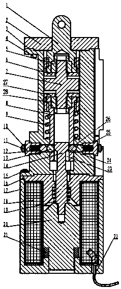
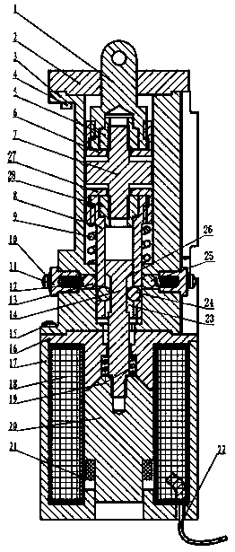
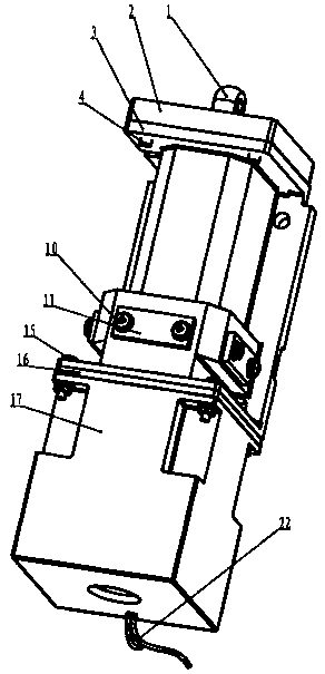
[0019] Example. An electromagnetic locking device, constituted as Figure 1-3 As shown, there is a casing III8, and a casing 3 is provided on the outside of the casing III8. A group of second mounting holes 25 are provided on the casing 3. Steel balls 13 are arranged in the second mounting holes 25, and a casing 38 is provided on the casing III8. A set of first mounting holes 24, a push rod 14 is provided in the casing III8, and a set of slots 23 are provided on the push rod 14, and one end surface of the slot 23 is a slope 26.

[0020] A spring I9 is ​​provided between the casing 3 and the casing III8.

[0021] The side of the steel ball 13 facing away from the push rod 14 is provided with a spring II12, one end of the spring II12 is located in the groove of the fixing block 11, and the fixing bl...


PUM


Abstract

The invention discloses an electromagnetic type locking device. The electromagnetic type locking device comprises a sleeve III, wherein a housing is arranged at the outer side of the sleeve III; a group of second mounting holes is formed in the housing; steel balls are arranged in the second mounting holes; a group of first mounting holes is formed in the sleeve III; a pushing rod is arranged in the sleeve III; a group of open slots is formed in the pushing rod; and one end surface of each open slot is an inclined surface. The invention provides a universal locking device for an emitting system, and the universal locking device can emit different devices, so that the beneficial effects of simplifying the emitting system, improving efficiency and reducing the cost are achieved. The electromagnetic type locking device further realizes three functions: firstly, an ignition process of the emitting system is an accelerated speed increasing process, so that an assembly must be locked, and system emission is prevented; secondly, accelerated speed of the emitting system reaches emitting requirements, and the assembly must be unlocked, so that system emission is realized; and thirdly, afteremission is completed, the assembly must return to the original state to wait for a re-filling emitting device.

Description

technical field [0001] The invention relates to a locking device, in particular to an electromagnetic locking device. Background technique [0002] At present, the launch system needs to achieve a certain acceleration before the launch device to maximize the flight distance. The locking devices used in the domestic launch system are all springs. When the additional force generated by the acceleration exceeds the spring preload, the lock The device is unlocked and the launch is performed. Since different devices require different accelerations, springs of different specifications need to be installed for launching different devices. Such a design leads to the lack of versatility in the locking device of the launching system. Every time a different device is launched, the launching system needs to be designed separately. Corresponding springs are used to launch different devices, which makes it extremely inconvenient to replace the locking device of the launching system and t...

Claims


Application Information

Patent Timeline
Patent Type & Authority Patents(China)
IPC IPC(8): F41B7/00
CPCF41B7/00
Inventor 王建雄马伟冯小林廖益龙刘凯张娟
Owner 贵州振华群英电器有限公司(国营第八九一厂)
Why Eureka
Try Eureka