Digital-feed ultra-wideband antenna

A technology of digital signals and narrow pulses, which is applied in the direction of antenna, electrical components, and radiating element structure, can solve the problems of complex structure, low spectrum utilization rate, and large volume at the sending end, and achieve simplified transmitter structure and improved Information transmission rate, effect of reducing channel interference

Inactive Publication Date: 2012-12-12
UNIV OF ELECTRONICS SCI & TECH OF CHINA
View PDF3 Cites 3 Cited by
  • Summary
  • Abstract
  • Description
  • Claims
  • Application Information

AI Technical Summary

Problems solved by technology

[0003] However, this conventional digital wireless communication technology inevitably has several limitations: firstly, the introduction of modulation technology will inevitably bring complex structure and huge volume to the sending end of the digital communication system; secondly, due to the limited bandwidth of the radio frequency modulator , the transmission capacity of the channel is difficult to improve; in addition, the existing digital modulation technology is still difficult to solve the problems of low spectrum utilization, poor anti-multipath fading ability, slow power spectrum attenuation, serious out-of-band radiation, etc.
The pulse generation circuit at the front end of the antenna uses an active FET transistor, so an additional DC bias circuit is required, which makes it difficult to integrate the circuit with the antenna, and the DC bias circuit will also bring some parasitic radiation to the antenna, which affects the performance of the antenna. radiation performance

Method used


Image

  • Digital-feed ultra-wideband antenna
  • Digital-feed ultra-wideband antenna
  • Digital-feed ultra-wideband antenna

Examples


specific Embodiment approach

[0024] The specific implementation of the antenna of the present invention is as follows:

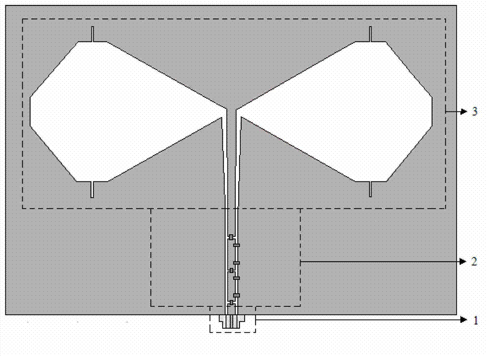
[0025] A data-fed ultra-wideband antenna of the present invention is printed on a rectangular printed board. The relative dielectric constant of the rectangular printed board is 4.4, the size is 60.5mm×91mm, and the thickness is 1mm;

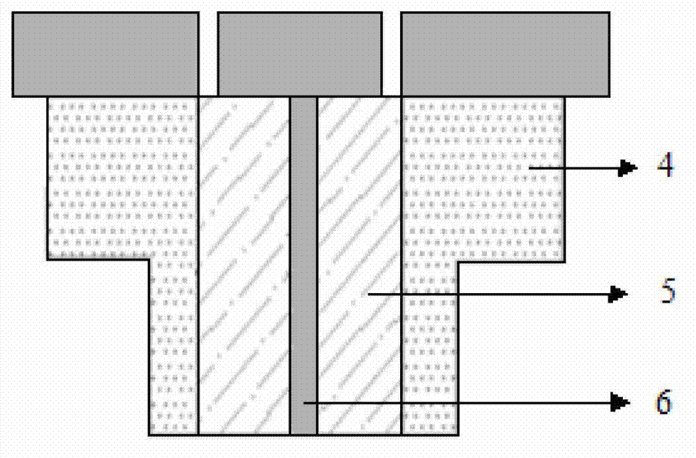
[0026]The digital signal input port adopts SMA connector, which is welded on one end of the 50-ohm coplanar waveguide. The inner conductor of the SMA connector is welded to the coplanar waveguide signal line, and the outer conductor of the SMA connector is welded to the two ground planes of the coplanar waveguide.

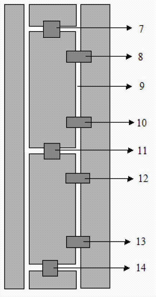
[0027] The digital drive SRD narrow pulse signal generator circuit is made on the coplanar waveguide, among which, the coupling capacitor: C1=68pF; the resonant circuit: L1, C2, L2 are 82nH, 48pF, 32nH respectively; the narrow pulse forming circuit: step recovery diode The (SRD) model is 2J3C produced by Chengdu Yaguang Electronics Co., Ltd....


PUM


Abstract

The invention discloses a digital-feed ultra-wideband antenna, belongs to the field of digital wireless communication and relates to non-modulation digital signal sending antennas. The digital-feed ultra-wideband antenna comprises a digital signal input port (1), a digitally-driven SRD (step recovery diode) narrow pulse signal generator (2) and a bow-tie slot radiating unit (3) which are in coplanar waveguide series connection, wherein the digital signal input port (1) is an SMA (sub-miniature-A) connector for feed-in of digital signals; the digitally-driven SRD narrow pulse signal generator (2) comprises a coupling circuit, a resonance matching circuit, a pulse forming circuit and a pulse shaping circuit; and the bow-tie slot radiating unit is used for radiating pulse signals. The digital-signal-driven pulse generator is used for generating pulse, and the pulse is radiated by the ultra-wideband bow-tie antenna, so that direct sending and wireless transmission of the digital signals can be achieved without pre-modulating the digital signals, and a sender structure of a digital wireless communication system can be greatly simplified. Additionally, digital information is transmitted by the ultra-wideband pulse, so that information transmission rate is increased beneficially, and channel interference is reduced.

Description

technical field [0001] The invention belongs to the field of digital wireless communication, and relates to a wireless communication method for non-modulated digital signals, in particular to an ultra-wideband transmitting antenna technology for non-modulated digital signals. Background technique [0002] In digital wireless communication, long-distance transmission cannot be carried out on wireless channels, because the digital baseband signal is a low-frequency signal, which is difficult to be efficiently transmitted by conventional antennas. Therefore, at the sending end, it is necessary to carry out carrier modulation on the digital signal, and modulate the digital baseband signal into a radio frequency signal, so that the spectrum of the baseband signal can be moved to a high frequency before it can be transmitted by the antenna and then wirelessly transmitted. [0003] However, this conventional digital wireless communication technology inevitably has several limitatio...

Claims


Application Information

Patent Timeline
Patent Type & Authority Applications(China)
IPC IPC(8): H01Q1/36H01Q23/00
Inventor 赵德双
Owner UNIV OF ELECTRONICS SCI & TECH OF CHINA
Why Eureka
Try Eureka