

Equipment for testing stability of power cabinet
A testing equipment and robustness technology, used in impact testing, machine/structural component testing, measuring devices, etc., and can solve problems such as large resource consumption, long time consumption, and many testing steps.
- Summary
- Abstract
- Description
- Claims
- Application Information
AI Technical Summary
Problems solved by technology
Method used
Image

Examples
Embodiment 1
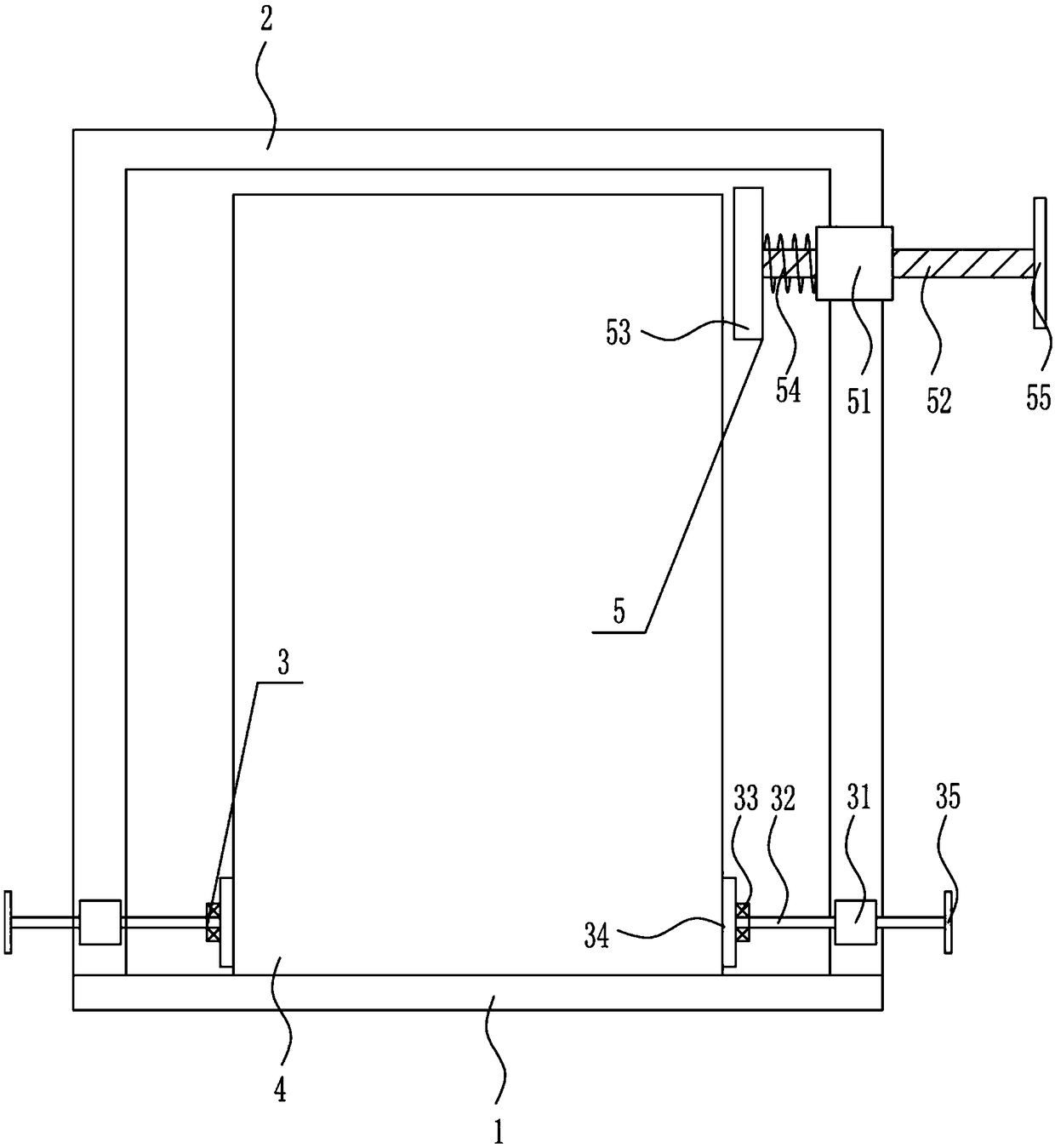
[0026] A power cabinet stability test equipment, such as Figure 1-2 As shown, it includes a base plate 1, an N-type frame 2, a fixing mechanism 3 and a testing mechanism 5. An N-type frame 2 is installed on the top of the base plate 1, a fixing mechanism 3 is installed on the N-type frame 2, and the right side of the top of the N-type frame 2 is installed. A test mechanism 5 is installed.
Embodiment 2
[0028] A power cabinet stability test equipment, such as Figure 1-2 As shown, it includes a base plate 1, an N-type frame 2, a fixing mechanism 3 and a testing mechanism 5. An N-type frame 2 is installed on the top of the base plate 1, a fixing mechanism 3 is installed on the N-type frame 2, and the right side of the top of the N-type frame 2 is installed. A test mechanism 5 is installed.
[0029] The fixing mechanism 3 includes a nut 31, a bolt 32, a first bearing seat 33, a first pressing plate 34 and a turning block 35. The left and right sides of the bottom of the N-shaped frame 2 are symmetrically provided with nuts 31, and the nut 31 is provided with a matching bolt. 32. The opposite ends of the left and right bolts 32 are symmetrically installed with a first bearing seat 33, the other side of the first bearing seat 33 is provided with a first pressing plate 34, and the other end of the bolt 32 is provided with a turning block 35.
Embodiment 3
[0031] A power cabinet stability test equipment, such as Figure 1-2 As shown, it includes a base plate 1, an N-type frame 2, a fixing mechanism 3 and a testing mechanism 5. An N-type frame 2 is installed on the top of the base plate 1, a fixing mechanism 3 is installed on the N-type frame 2, and the right side of the top of the N-type frame 2 is installed. A test mechanism 5 is installed.
[0032] The fixing mechanism 3 includes a nut 31, a bolt 32, a first bearing seat 33, a first pressing plate 34 and a turning block 35. The left and right sides of the bottom of the N-shaped frame 2 are symmetrically provided with nuts 31, and the nut 31 is provided with a matching bolt. 32. The opposite ends of the left and right bolts 32 are symmetrically installed with a first bearing seat 33, the other side of the first bearing seat 33 is provided with a first pressing plate 34, and the other end of the bolt 32 is provided with a turning block 35.
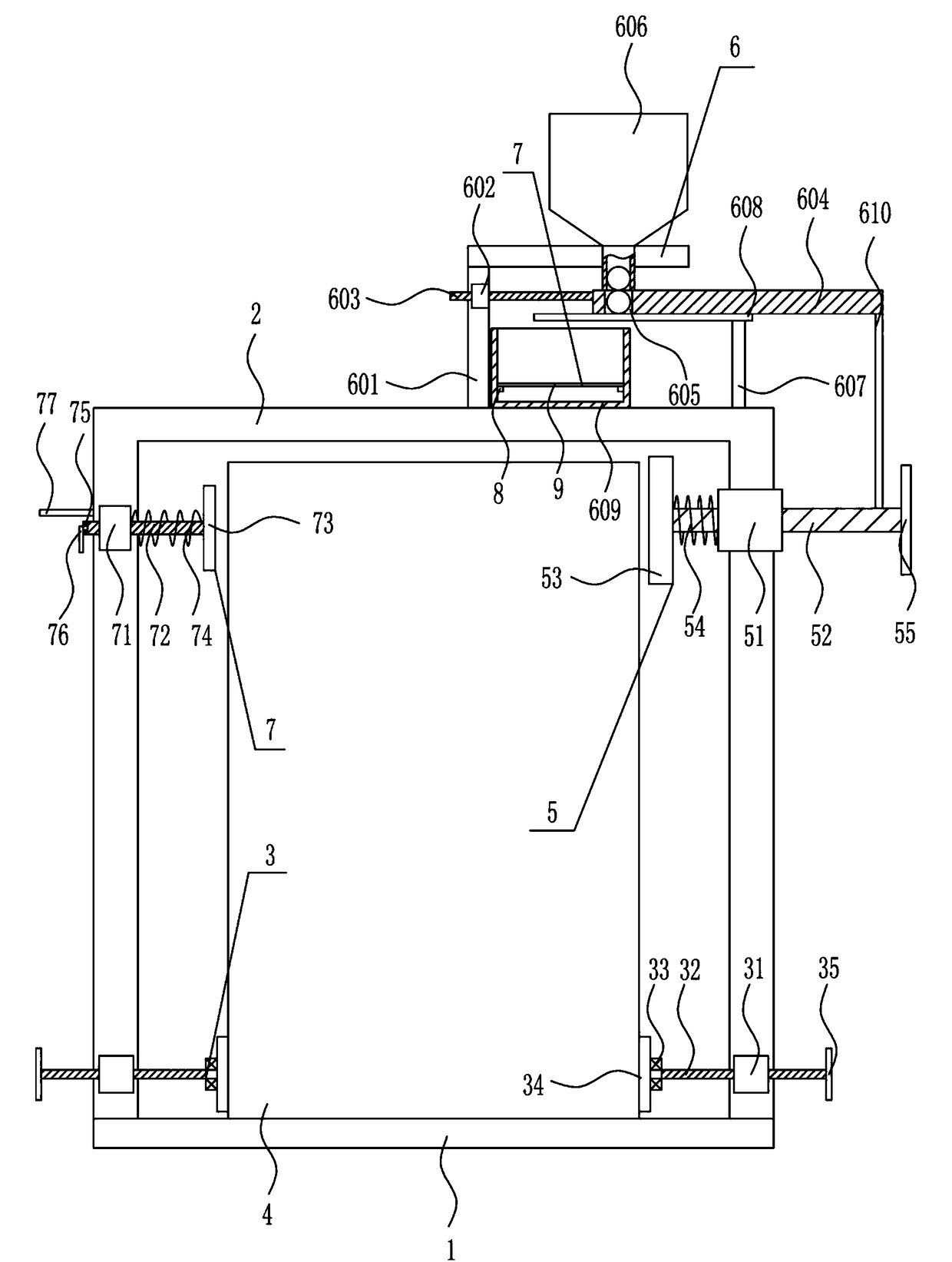
[0033]The testing mechanism 5 includ...
PUM
 Abstract
Description
Claims
Application Information