Methods and devices for testing downlink and uplink wireless indexes of active antenna system

An active antenna and wireless index technology, applied in the field of communication, can solve the problems that no solution has been proposed, the antenna performance and index test of the active antenna system cannot be performed, and the antenna gain and pattern cannot be tested.

Active Publication Date: 2012-09-19
NANJING ZHONGXING SOFTWARE
View PDF4 Cites 25 Cited by
  • Summary
  • Abstract
  • Description
  • Claims
  • Application Information

AI Technical Summary

Problems solved by technology

[0004] Using conduction test to measure the radio frequency index of the active part of the active antenna system will cause the active antenna system to be split into the active part and the antenna part; this will increase redundant interfaces, thus destroying the integrity of the active antenna system;
[0005] The conduction test cannot test the gain, pattern and other indicators of the antenna, and the performance test of the antenna index of the active antenna system still needs to be carried out in the antenna test field environment;
[0006] The performance and index test of the antenna part of the active antenna system requires the configuration of the weig

Method used


Image

  • Methods and devices for testing downlink and uplink wireless indexes of active antenna system
  • Methods and devices for testing downlink and uplink wireless indexes of active antenna system
  • Methods and devices for testing downlink and uplink wireless indexes of active antenna system

Examples


Embodiment 1

[0059] This embodiment provides a method for testing downlink wireless indicators of an active antenna system, which mainly includes several steps:

[0060] 1. Test environment calibration

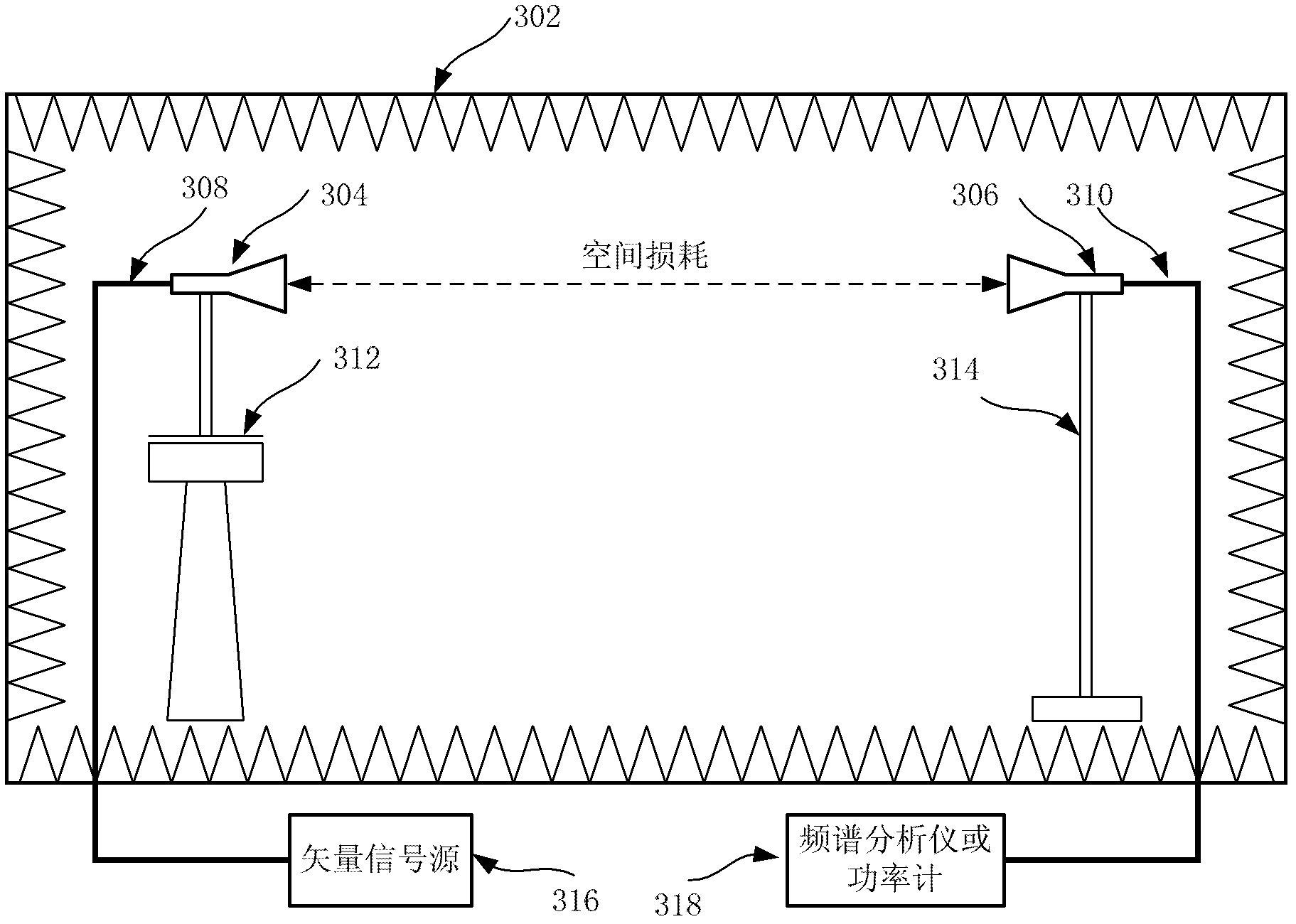
[0061] Such as image 3 shown. Under the darkroom environment 302, the gain reference antenna 304 is installed on the antenna turntable 312, and is connected to the vector signal source 316 through the radio frequency cable 308, and the other end, the receiving antenna 306 is installed on the antenna bracket 314, and connected to the vector signal source 316 through the radio frequency cable 310. Spectrum analyzer (or power meter) 318 on.

[0062] according to image 3 After setting up the test environment, follow the Figure 4 The processing flow for environmental calibration:

[0063] Step S402 , adjusting the turntable 312 and the antenna bracket 314 so that the gain reference antenna 304 is aligned with the receiving antenna 306 in the forward direction.

[0064] Step S404 , set ...

Embodiment 2

[0108]This embodiment provides a method for testing uplink wireless indicators of an active antenna system, which mainly includes several steps:

[0109] 1. Test environment calibration, similar to embodiment 1, but, in the uplink wireless test, combined with formula (2), EIRS can be expressed as:

[0110] EIRS=Rs-Gr=Ps-(Lx-Gh+Ls)=Ps-ΔPc (4)

[0111] Among them, Rs is the received power level detected by the active antenna system.

[0112] 2. According to Figure 9 The test environment shown is set up. In the darkroom environment 902, the active antenna system 904 is installed on the antenna turntable 912, and is connected to the baseband processing unit 916 through the optical fiber 908. At the other end, the transmitting antenna 906 is installed on the antenna bracket 914. The useful signal The signals from the source 918 and the interference signal source 920 can be combined through a combiner 922 . Connect to transmit antenna 906 via radio frequency cable 910 . The vec...


PUM


Abstract

The invention provides methods and devices for testing downlink and uplink wireless indexes of an active antenna system. The method for testing the downlink wireless index is carried out in a wave-absorbing dark room or a signal non-interference space and comprises the following steps of: acquiring calibration parameters of the wave-absorbing dark room or the signal non-interference space; configuring the active antenna system to transmit a wireless wave beam to a receiving antenna, wherein the wireless wave beam is triggered and generated by a base-band signal from a base-band processing unit outside the wave-absorbing dark room or the signal non-interference space, and then transmitted to a test instrument outside the wave-absorbing dark room or the signal non-interference space through the receiving antenna; and starting the base-band processing unit and the active antenna system, and testing the wireless indexes of the adjusted active antenna system according to the calibration parameters. By adoption of the technical scheme provided by the invention, testing of various wireless indexes of the active antenna system is realized.

Description

technical field [0001] The present invention relates to the communication field, in particular to a method and device for testing downlink and uplink wireless indicators of an active antenna system. Background technique [0002] The active antenna system is a base station communication system in which multi-channel transceivers and base station antennas are integrated. Such as figure 1 As shown, in the active antenna system 10, the multi-channel digital intermediate frequency processing module 100 performs baseband data transmission with the baseband processing unit 12; the multi-channel analog transceiver channel 102 converts the digital signal into a downlink analog radio frequency signal or an uplink analog signal to be received converted into digital signals; the multi-channel analog transceiver channel 102 transmits and receives wireless signals through the antenna unit array 104 . [0003] At present, the traditional wireless base station test adopts the conduction t...

Claims


Application Information

Patent Timeline
IPC IPC(8): H04B17/00H04B17/21
Inventor 雷龙刚王鹏王博明李香玲
Owner NANJING ZHONGXING SOFTWARE
Why Eureka
Try Eureka