Rotating connection power supply bracket

A technology of rotating connection and screw connection, applied in the field of rotating connection power supply bracket, can solve problems such as difficulty in supplying power to rolling elements, and achieve the effects of avoiding poor contact, solving power supply difficulties, and reducing friction

Inactive Publication Date: 2018-10-23
朱森
View PDF0 Cites 2 Cited by
  • Summary
  • Abstract
  • Description
  • Claims
  • Application Information

AI Technical Summary

Problems solved by technology

[0003] The object of the present invention is to solve the above-mentioned existing problems and provide a rotating connecti

Method used


Image

  • Rotating connection power supply bracket
  • Rotating connection power supply bracket
  • Rotating connection power supply bracket

Examples


Embodiment 1

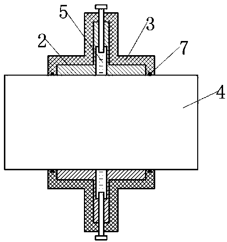
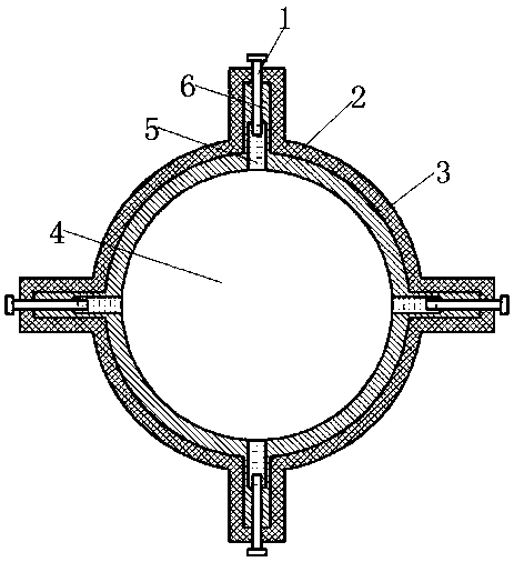
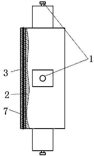
[0027] A rotating connection power supply bracket, the power supply bracket includes a slip ring 2, a support arm 6 and a terminal 1; the support arm 6 is integrally formed with the slip ring 2, and the front end of the support arm 6 is fixedly connected to the outer wall of the slip ring 2, Such as figure 1 As shown, the support arm 6 is perpendicular to the outer wall of the slip ring 2, so that the section at the joint between the slip ring 2 and the support arm 6 is in the shape of a "T"; the support arm 6 and the slip ring 2 are both conductors, and the inside of the support arm 6 An effusion cavity 5 is provided, the front end of the effusion cavity 5 extends toward the direction of the slip ring 2 and penetrates through the wall of the slip ring 2, forming an opening on the inner wall of the slip ring 2; a conductive liquid is arranged in the effusion cavity 5; There is also a threaded hole in the support arm 6, the front end of the threaded hole communicates with the r...


PUM


Abstract

A rotating connection power supply bracket includes a slip ring, a support arm and a binding post. The support arm and the slip ring are integrally formed. The front end of the support arm is fixedlyconnected to the outer wall of the slip ring. The support arm and the slip ring are conductors. The support arm is provided therein with a liquid chamber. The front end of the liquid chamber extends toward the slip ring and penetrates through the wall of the slip ring to form an opening on the inner wall of the slip ring. The liquid chamber is filled with a conductive liquid. A threaded hole is disposed in the support arm. The front end of the threaded hole communicates with the rear end of the liquid chamber. The rear end of the threaded hole penetrates through the rear end of the support arm. The support arm is provided with the binding post. The binding post is inserted into the threaded hole from the rear end of the threaded hole and is in threaded connection with the threaded hole. The binding post is configured to be connected with a power source. The power supply bracket can solve the problem that it is difficult to supply power to a rolling element in a rotating state.

Description

technical field [0001] The invention relates to the field of movable power supply, in particular to a rotating connection power supply bracket. Background technique [0002] Install a rolling body on the bracket, insert the rolling body into the mounting hole on the bracket, and make the rolling body rotate in the mounting hole on the bracket; when the rolling body needs to supply power to the rolling body during the rotation, many difficulties will arise; first , the wire cannot be fixedly connected directly to the rolling body. If the guide is directly connected to the rolling body, the rolling body will knot the wire during the rotation process, and the wire will also affect the rotation of the rolling body; if the wire is connected to the bracket, The power supply is supplied through contact between the mounting hole on the bracket and the contact surface of the rolling body. If the rolling body and the inner wall of the mounting hole are worn during the rotation, there ...

Claims


Application Information

Patent Timeline
IPC IPC(8): H01R39/64
CPCH01R39/646H01R39/643
Inventor 朱森
Owner 朱森
Why Eureka
Try Eureka