Differential protection locking method for tail current of series transformer

A series transformer and differential protection technology, applied in the direction of emergency protection circuit devices, electrical components, etc., can solve the problems of trailing current differential protection misoperation, etc., to prevent trailing current misoperation, short calculation time, and speed of discrimination fast effect

Active Publication Date: 2018-10-23
NR ELECTRIC CO LTD +2
View PDF5 Cites 3 Cited by
  • Summary
  • Abstract
  • Description
  • Claims
  • Application Information

AI Technical Summary

Problems solved by technology

[0006] The technical problem to be solved by the present invention is: to overcome the problem that the trailing current existing in the series transformer bypass closing may cause differential protection misoperation, and to provide a differential protection blocking method for the trailing current of the series transformer

Method used


Image

  • Differential protection locking method for tail current of series transformer

Examples


Embodiment Construction

[0016] Attached below figure 1 The present invention is further described. The following examples are only used to illustrate the technical solution of the present invention more clearly, but not to limit the protection scope of the present invention.

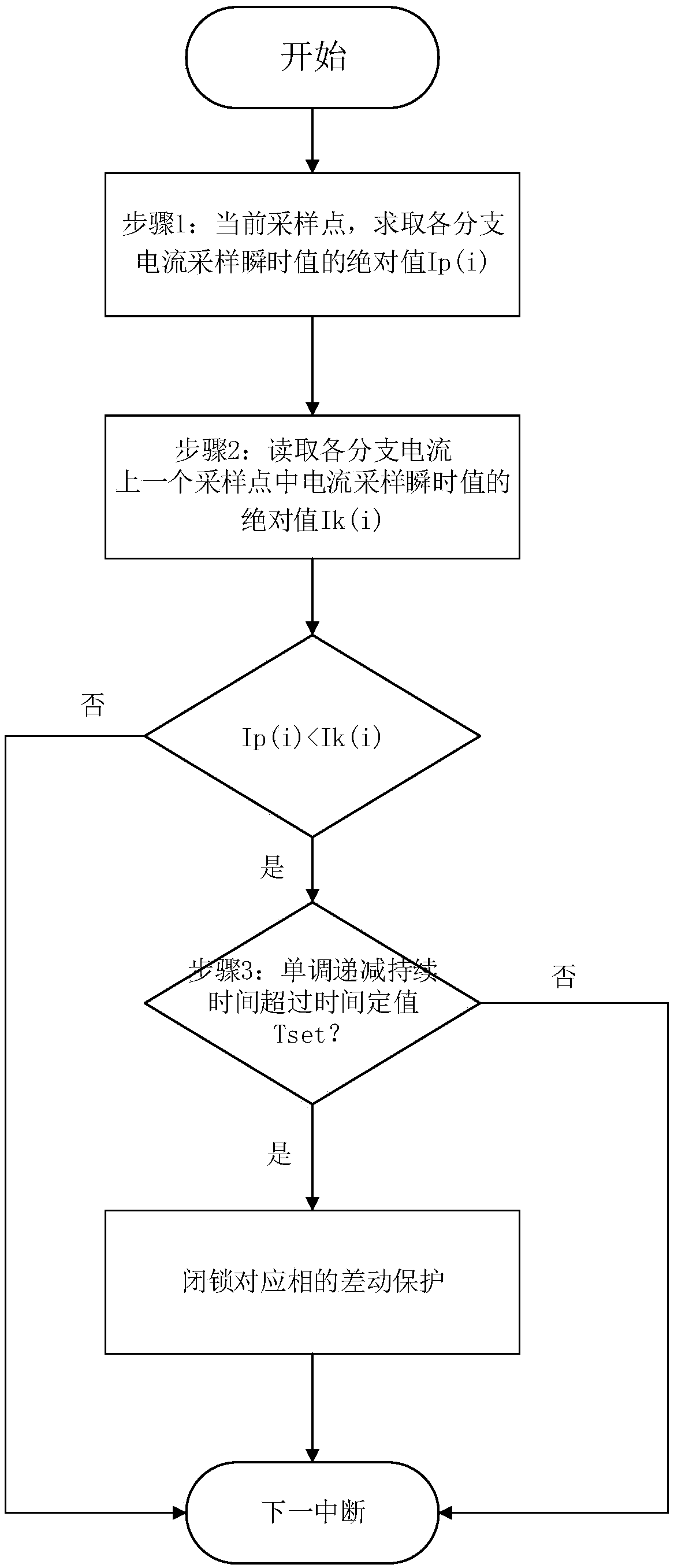
[0017] figure 1 Shown is the flow chart of judging the trailing current of the series transformer. A differential protection blocking method for trailing current of a series transformer of the present invention comprises the following steps,

[0018] Step 1, define the maximum number of branches of the differential protection as n, and take the absolute value of the sampling instantaneous value of the current sampling point of the i branch current as Ip(i);

[0019] Step 2, compare Ip(i) with the absolute value Ik(i) of the sampling instantaneous value of the i-th branch current at a sampling point; if Ip(i)


PUM


Abstract

The invention provides a differential protection locking method for the tail current of a series transformer. The tail current is determined by utilizing the trend of a current sampling value in the phase current, differential protection is locked according to the phase, the tail current can be determined more accurately, protection is not refused during a fault, protection is not carried out formistake when the tail current occurs in the CT, accidents are prevented from expanding, and safe and stable operation of the power grid can be guaranteed more effectively.

Description

technical field [0001] The invention belongs to the field of relay protection of electric power systems, and in particular relates to a differential protection blocking method for trailing current of series transformers. Background technique [0002] The application occasions and wiring forms of series transformers are quite different from ordinary transformers. [0003] The series transformer adopts the way of bypass closing to isolate the transformer. When the series transformer is in normal operation, the bypass switch is in an open state. At this time, the current flowing through the grid side winding of the series transformer is the line flow. When the bypass switch is closed, the two ends of the series transformer winding are completely short-circuited. [0004] Since the transformer is an inductive component, when the series transformer winding is short-circuited, the current in the series transformer winding cannot change abruptly, and an attenuated DC component wi...

Claims


Application Information

Patent Timeline
Patent Type & Authority Applications(China)
IPC IPC(8): H02H7/045
CPCH02H7/045
Inventor 王毅顾乔根陈建民张晓宇邱智勇文继锋韩学军程骁郑超吕航莫品豪龚啸倪腊琴刘中平骆敬年章耀耀
Owner NR ELECTRIC CO LTD
Why Eureka
Try Eureka